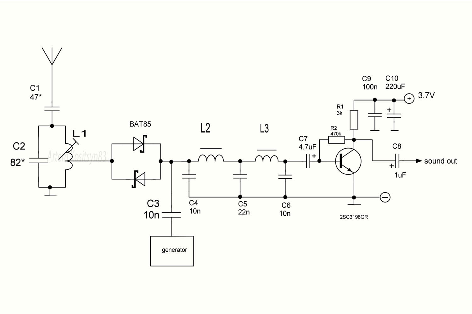
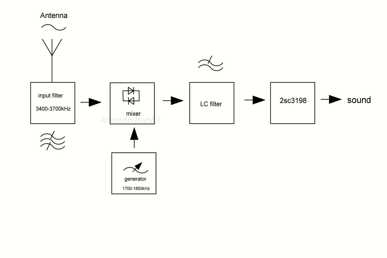
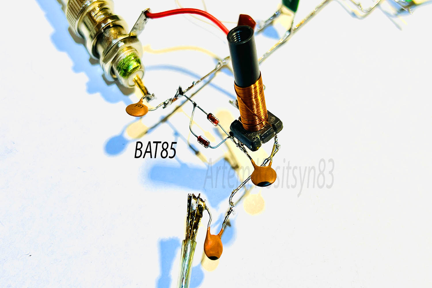
Direct conversion receiver. Such radio receivers are capable of excellent reception of CW signals and single-sideband SSB signals. Usually you can hear such signals on short waves, this is how radio amateurs communicate at large distances from each other. To receive their signals as well as service signals, it is enough to do radio receiver which I will tell you about. How does such a radio receiver work? A signal from a radio station with a frequency of, say, 3000 kHz enters the mixer. The mixer also receives a signal from the generator, say, also with a frequency of 3000 kHz. There will be no sound signal at the output of the mixer, because there will be no signal beats. But if the frequency of the generator or the receiving signal changes to, say, 100 Hz , then you will hear these 100 Hz, this is the beat signal. The direct conversion receiver operates on beats. A filter is made on L1 and C2 that passes the useful signal at frequencies of approximately 3400-3700 kHz. This filter receives a signal from radio stations from the antenna. The selected signal goes to a mixer made of two Schottky diodes. The same mixer receives a signal from a generator, frequency which must be retuned, it is they who need to tune in to the signals of radio stations. But the frequency of the generator is chosen two times lower than the received one. Why is this done? The thing is that each diode will switch at its own half-wave of the sinusoidal signal, that is, the mixer will operate at twice the generator frequency. As a result, a useful sound signal (beats) and other high-frequency signals will appear at the mixer output. These high-frequency signals must be filtered. This is done by the L2-L3 C4-C6 filter. At the output of this filter there will be a sound signal, but it is very, very quiet and needs to be amplified. This is done by the 2sс3198 transistor. Next, the signal goes to the input of the low-frequency amplifier.
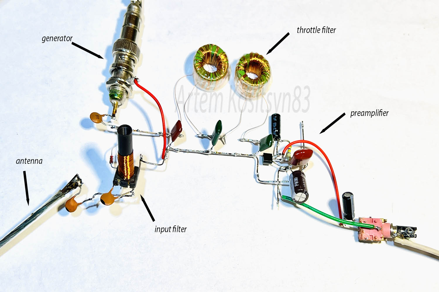
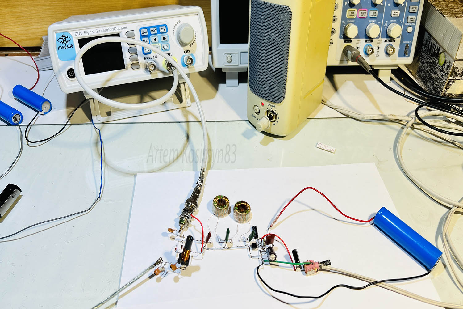
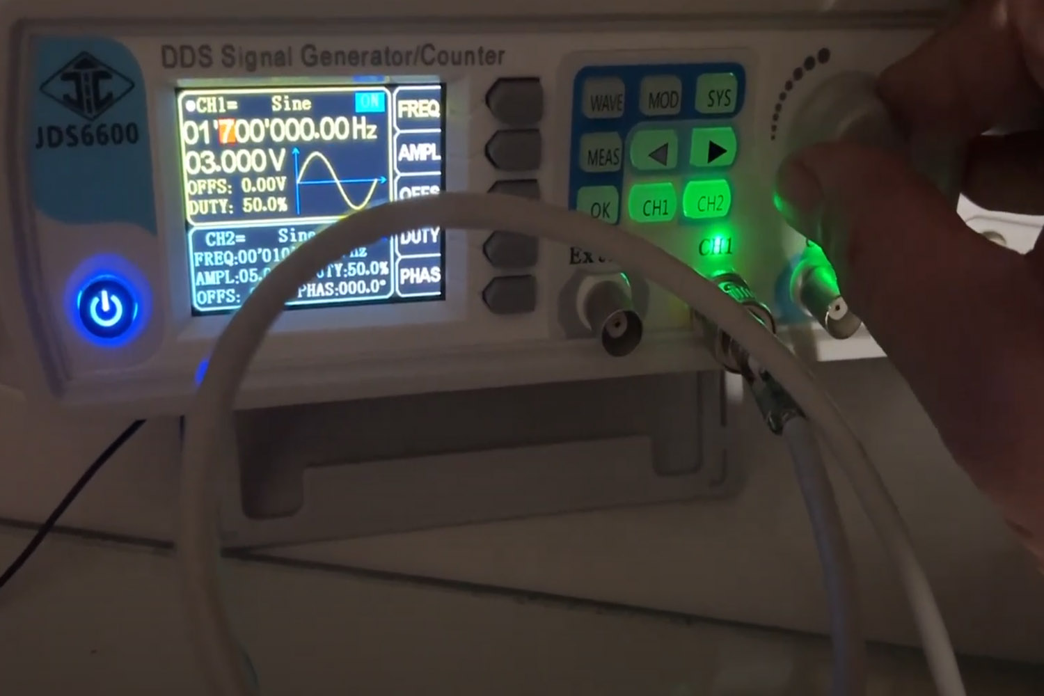
L1 is wound on a frame with a diameter of 6 mm and contains 46 turns of wire with a diameter of 0.14 mm with a tap from the 6th turn from the bottom according to the diagram.The coil contains a ferrite core.When you screw it in, you will hear a loud hiss of ether, this means that everything is in order.But in fact, this L1-C2 filter is better adjusted using instruments.You can also use other Schottky diodes, the most important thing is that they make less noise. Due to their noise, the reception quality may be poor.Chokes L2-L3 with an inductance of about 30 mH, I will tell you how they were made in another article.The tunable generator should operate at frequencies of approximately 1700-1900 kHz.It can be done using a single transistor; I used a signal generator.The peak-to-peak amplitude of the generator signal should be approximately 3 Volts.
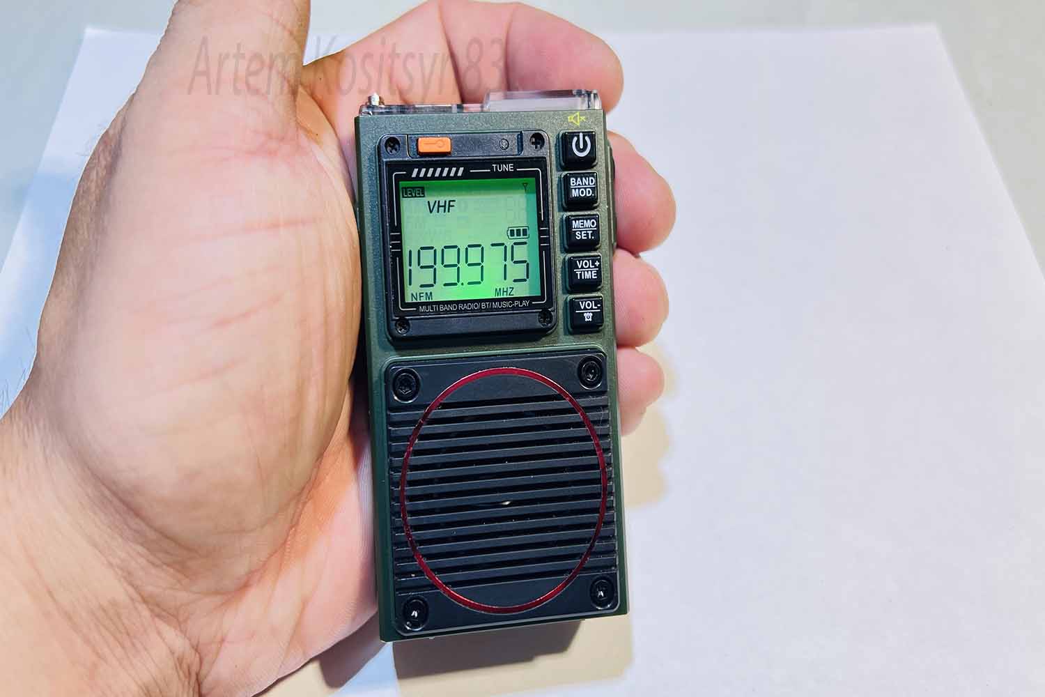
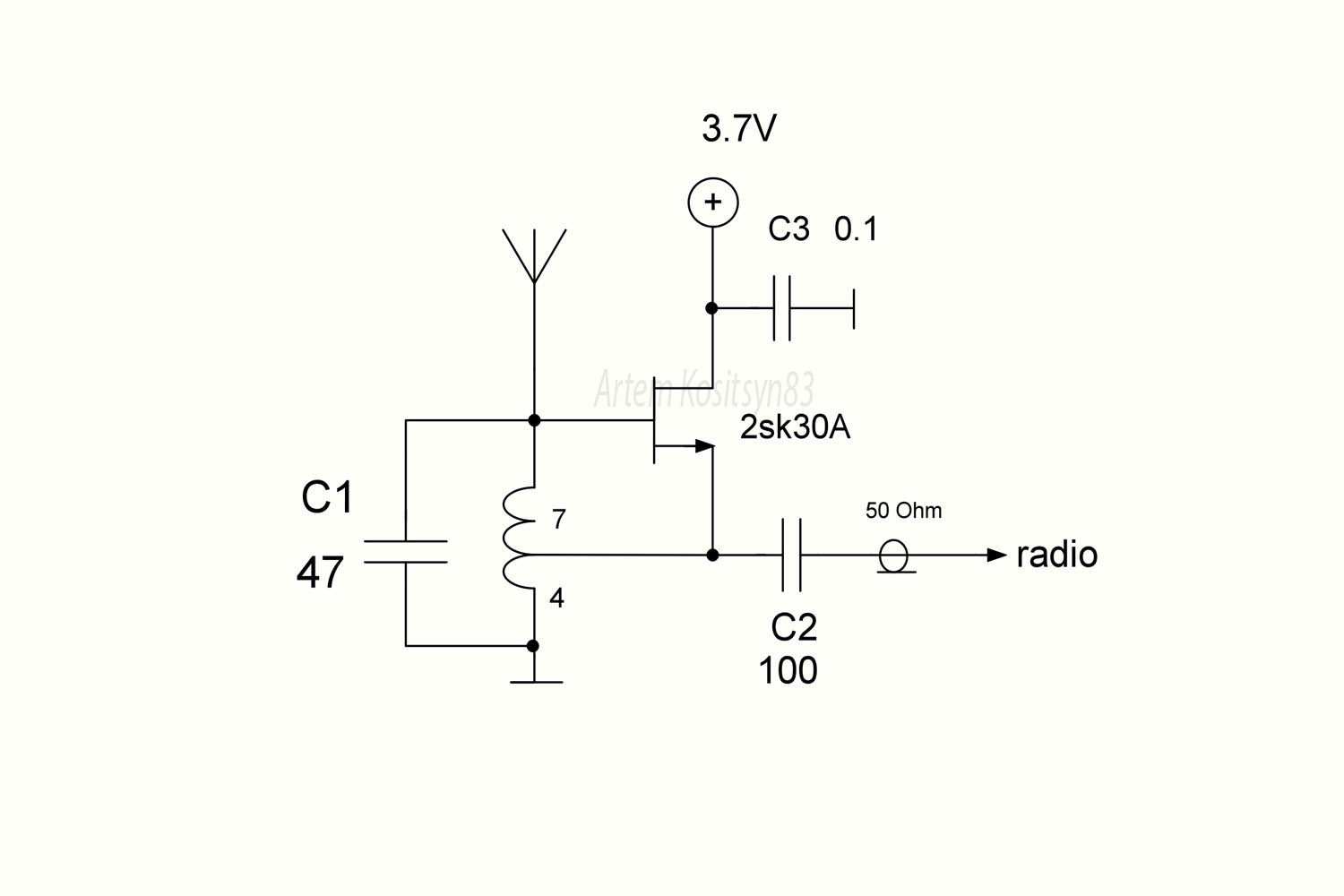
I used the antenna in the form of a wire 40 meters long. In the evening, I received a lot of signals from amateur radio station using this antenna. It is very important that there is no interference from switching power supplies during operation of the radio receiver. Turn off all sources of interference from the power supply. The cable from the signal generator must be shielded, otherwise it will emit a signal and direct the signal to the antenna, this will lead to unwanted interference. The receiver is powered by a 3.7 Volt battery, it is advisable to also power the signal generator from a battery or the generator power should be well filtered from interference.You must select capacitor C1 depending on your antenna and reception conditions. It is needed to reduce the level of interference, but at the same time the level of the useful signal decreases. But the interference decreases more than the useful signal.