Saving energy-saving lamps are now a thing of the past, and they have been replaced by LED lamps.In this article I will tell you how these lamps are arranged, the principle of their operation and the electronic ballast.
The bulb of the lamp consists of a white fluorescent emitter that glows when high voltage is applied.To get this voltage, there is a board inside the lamp – an electronic ballast that outputs a high-frequency voltage to ignite the lamp.Ballast is also called EPRA – an electronic starting device, before energy-saving lamps it looked like a heavy throttle valve together with a starter.
I disassembled one of the lamps and drew a circuit using printed conductors, I tested it and it works.
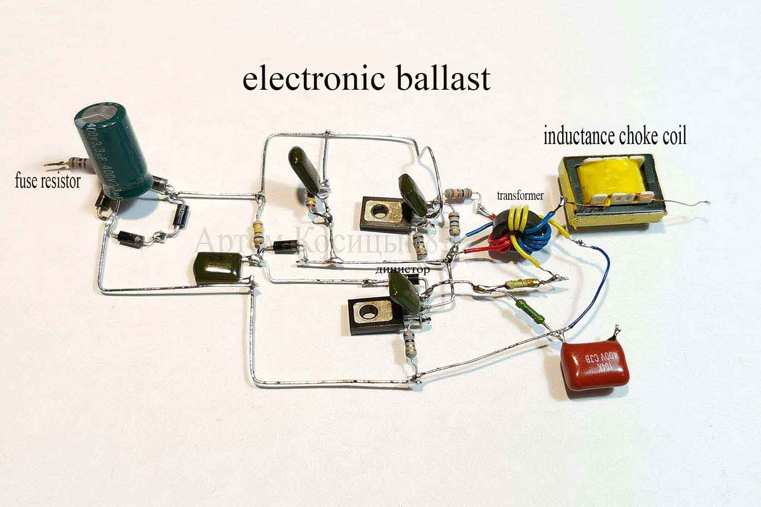
On the lamp board you can see a fuse resistor, it serves as a fuse and current limiter for the capacitor during power supply.You will also see a rectifier on a diode bridge and a 400 Volt capacitor.Two transistors, a choke and a transformer on the ring.How does this electronic ballast work?
When connected to the network, the rectifier will have a constant voltage of the amplitude value of the network-about 310 Volts.This voltage feeds a two-stroke half-bridge generator, which is assembled on two transistors.These transistors are alternately switched thanks to a transformer on a ferrite ring, the windings of which are wound in antiphase with respect to the bases of the transistors.A DB3 type dinistor is used to start the generator.As soon as the voltage on the capacitor C5 reaches the breakdown voltage of the dinistor, the pulse of positive polarity will enter the base of the transistor T2 and it opens,then there is shunting the dinistor with a diode D5 and the dinistor does not take part in the further operation of the generator.
Choke and capacitor C6, which is designed for a high voltage of about 1200 volts, and capacitor C7 is a series resonant circuit.As soon as we turn on the lamp, a high voltage pulse of the order of hundreds of Volts (about 900 Volts) is applied to the lamp for a short period of time.This is necessary to ignite the gas in the lamp.Further, a low resistance appears between the lamp spirals during the lamp glow, because the gas begins to conduct current inside the lamp and at the same time the high-voltage capacitor C6 is shunted and the high-voltage resonance stops, while the high voltage on lamp A reduces the current supplied to the lamp, restricts the throttle.Now the lamp has switched to operating mode, and the voltage on the bulb of the lamp is about 200 Volts with a frequency of about 25 kHz, this is with my circuit.
In the transistors 13003 themselves, there is a damping diode between the collector and the emitter, which serves to protect them from EMF pulses from the transformer windings.A capacitor C2 and a resistor R2 are also used for this.
I connected my device to the lamp and everything works fine.The power of the generator can be increased by changing the transistors.Transistors 13003 can be used in lamps with a power of up to 15 watts, 13006 for 75 watts, but transistors 13009 can be used for lamps with a power of up to 150 watts.Working ballasts of energy-saving lamps today can be used as ballast for bactericidal lamps or ultraviolet lamps.