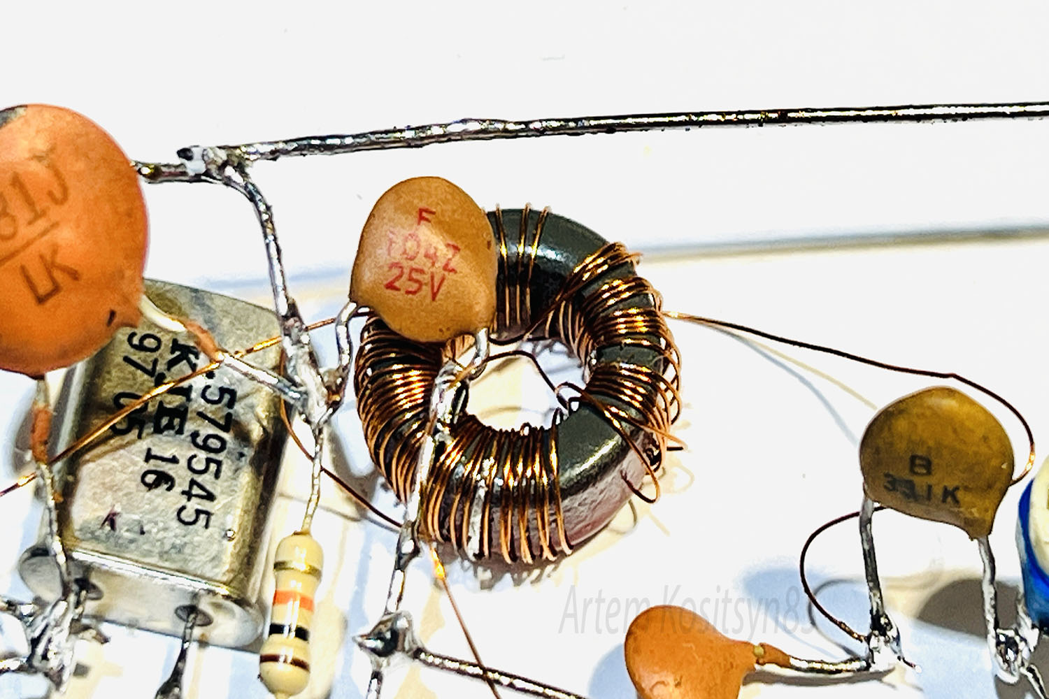
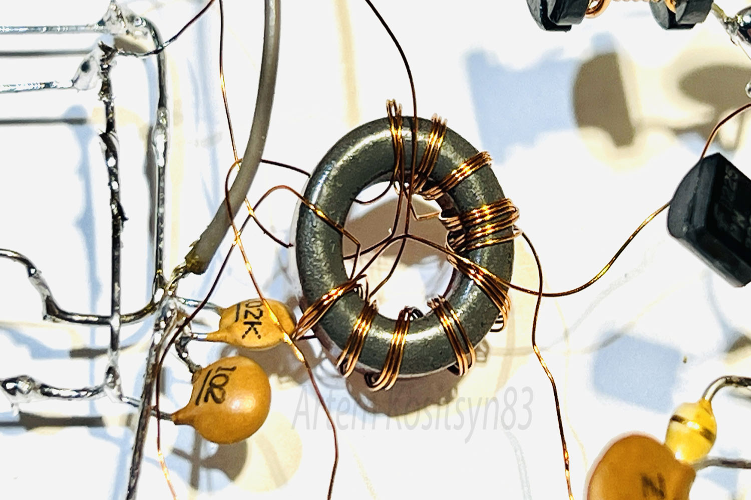
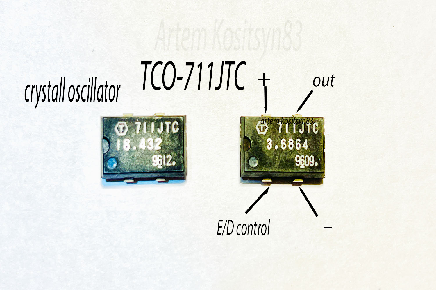
A simple single-sideband radio transmitter with which you can carry out radio communications over very long distances. The transmitter is built on the principle of phase shift. A generator is assembled on transistor VT1 at the frequency of a quartz resonator. An RC circuit C5-R4 is connected to winding L2, which shifts the generator signal by 90 degrees. Same the most 90-degree shift is made by C10-R7, but already in the low-frequency part. These two signals go to a balanced modulator using four BAT85 diodes. The output of this modulator will be a single-sideband signal, with a suppressed carrier and one sideband. A pre-amplifier is assembled on the VT3 transistor and on VT4 a power amplifier is assembled, but without an output filter. At a frequency of 3.5 MHz, I clearly heard my signal on a websdr receiver which is located at a distance of 2500 kilometers. I used a Fuchs antenna with a 40-meter long wire dropped down from a height of the 10th floor. Windings L1-L2 L5-L6 are wound on ferrite rings brand T50-2 measuring 13 * 7.5 * 5 mm. Winding with wire with a diameter of 0.14 mm. Winding L1 contains 50 turns and L2 contains 20 turns of wire. Winding L5 contains 20 turns with a tap from the middle,L6- 10 turns. If there is no signal on winding L6, then swap the leads of one of the windings L5.
I used a transformer from a tape recorder. Its high-resistance winding has a resistance of 1800 Ohms and the low-resistance winding has 14 Ohms. You can use another transformer with other windings. You will need to select the resistance of resistor R5 so that the amplitudes of the two signals on the RC chain R7 C10 are as equal as possible.
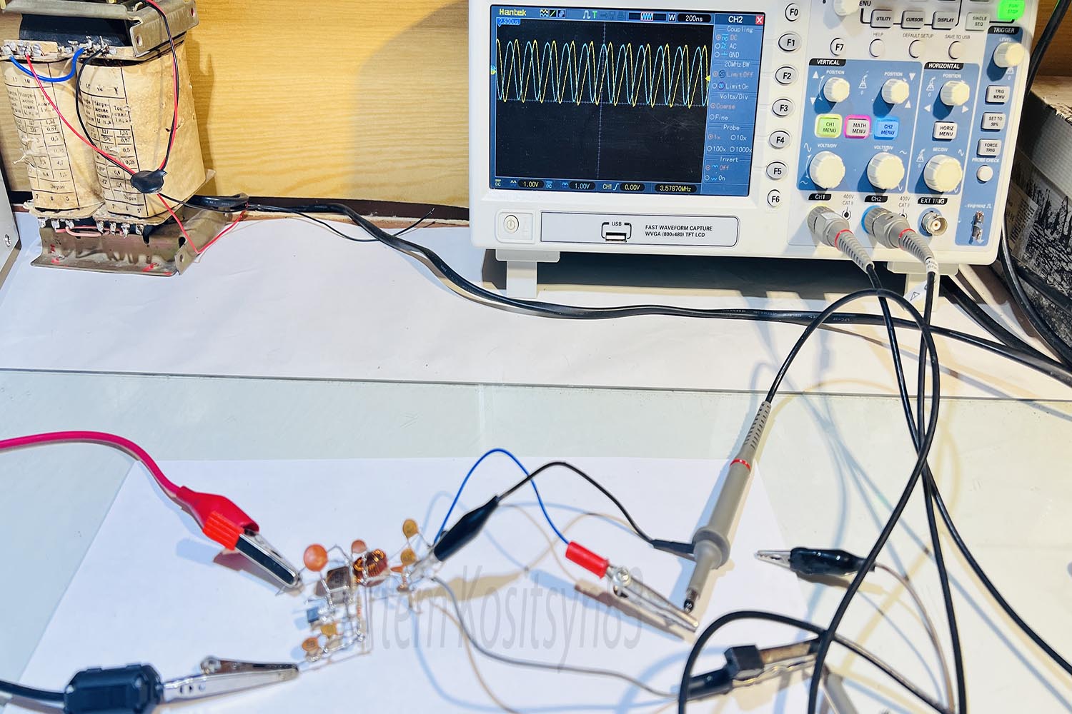
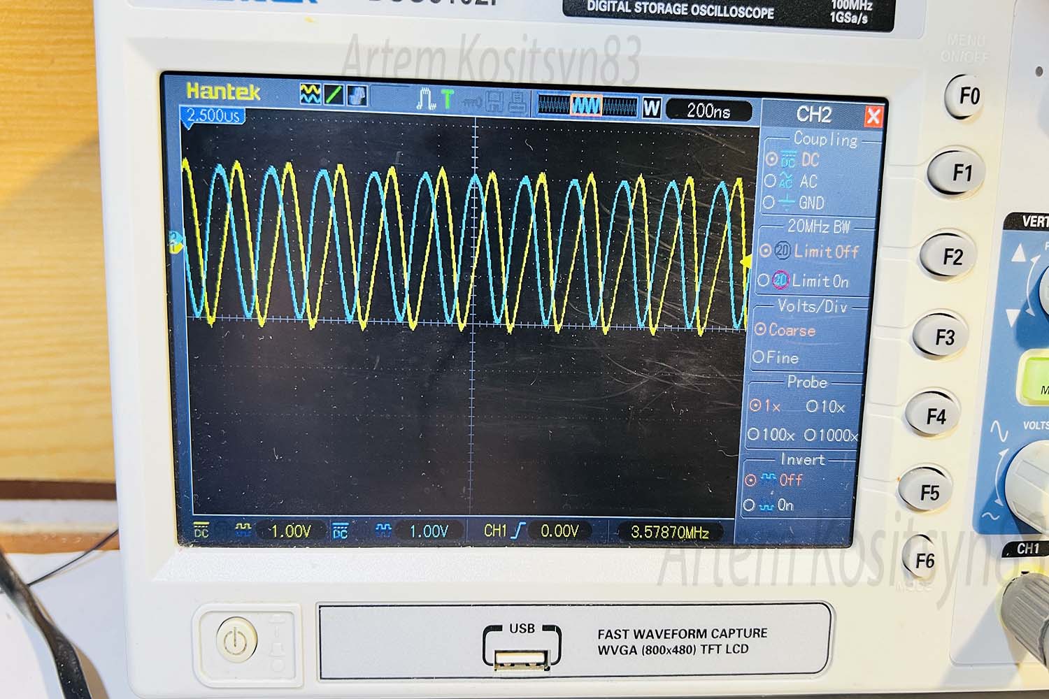
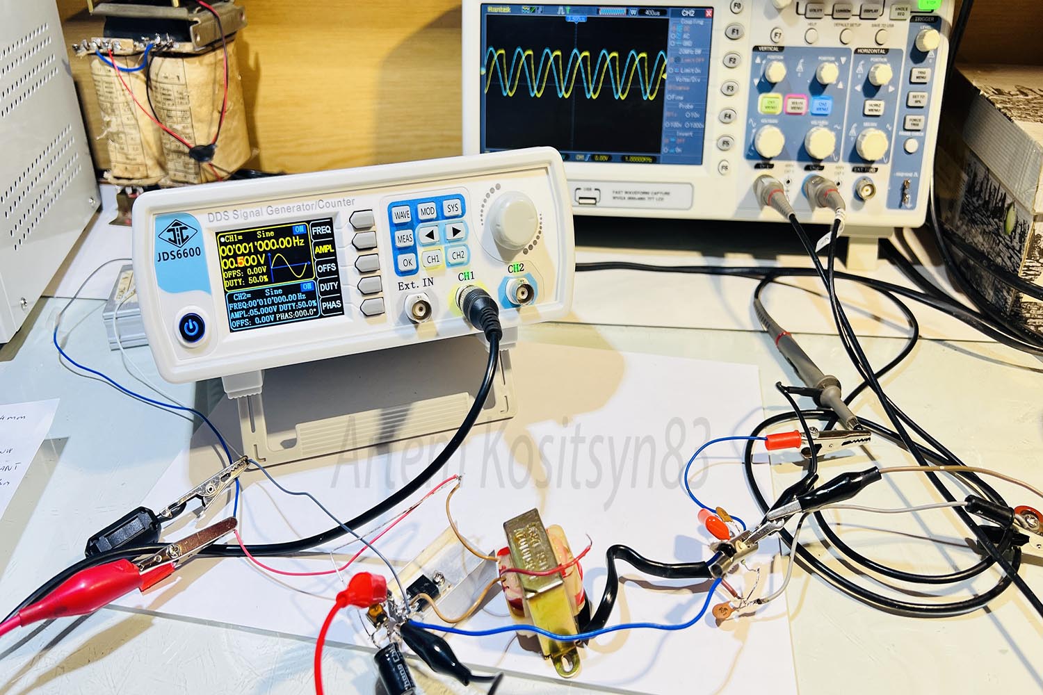
How to set up the transmitter. Connect two oscilloscope inputs to capacitors C6 C7 and turn on the generator on transistor VT1. You will see two signals shifted in phase by 90 degrees and preferably with the same amplitude. If the amplitudes are different, select the resistance of resistor R4. Do the same with the low-frequency part.Connect the two inputs of the oscilloscope to capacitors C8-C9 and apply a sinusoid signal with a frequency of 1000 Hz and an amplitude of approximately 200 mV to the input of transistor VT2. You will also see two signals shifted by 90 degrees. It is advisable to connect an audio amplifier chip instead of transistor VT2 or place it at the source of the transistorlow resistance resistor.
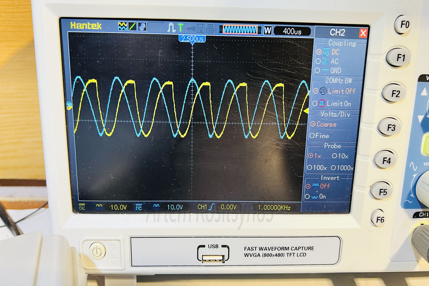
Here I adjust the low frequency part to 90 degrees
I used Schottky diodes BAT85. The IRF510 transistor is installed on the heat sink. Using resistor R15, set the current consumption of the IRF510 transistor to the maximum signal amplification in the antenna.
The current consumption will be about 1.5 Amperes at a voltage of 13 Volts
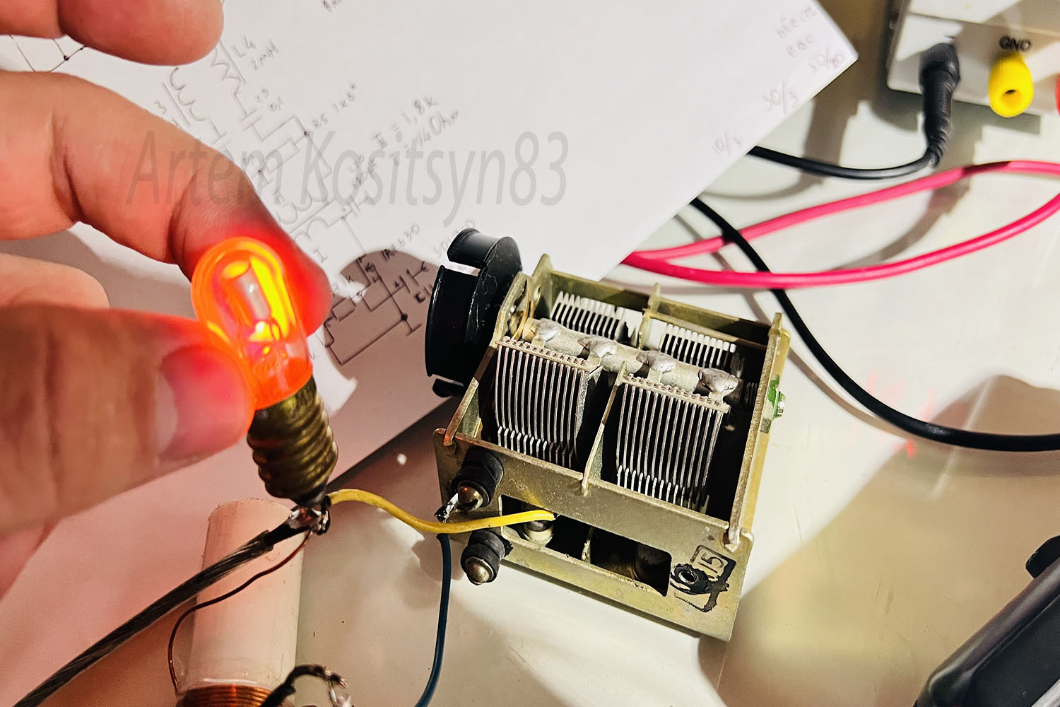
On the matching device of the Fuchs antenna, the neon lamp will glow in your hands from the HF voltage. I received my signal in the evening at a distance of 1400 kilometers and at 2500 kilometers