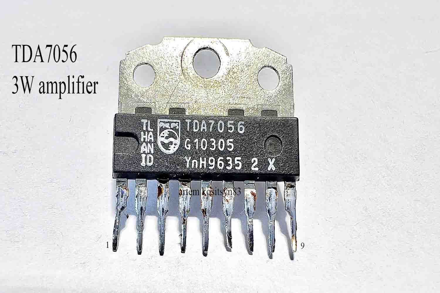
The TDA7056 chip is a 3-watt low-frequency monophonic amplifier with a bridge output and single-ended power supply. You can see such a chip on the circuit boards of old TVs. shutdown, low power consumption, output short circuit protection, ESD protection on all terminals,
Here are the main characteristics of the microcircuit:
Here is the amplifier circuit on this chip. Capacitors C3 and C3 are required for power, without them the current consumed in silent mode will be hundreds of mA. Resistor R1 controls the volume or sets the desired load resistance for the signal source.In silent mode, the current consumption should be a few mA
Attention!The resistor R2 must be constant.They cannot change the volume of the sound.If you put an alternating resistor in its place, then you will change the current consumed.The volume is controlled only by resistor R1.
The heat dissipation chip is installed on the radiator. The speaker resistance should be closer to 16 ohms. Now check the amplifier for the amplitude-frequency characteristic. Instead of the speaker, I connected an 8 Ohm resistor to the load. I send a signal from the generator at a level of 85 mV to the amplifier input. I connected the oscilloscope probes to the resistor.
By changing the frequency on the generator, I look at the signal. As you can see, the signal level at frequencies from about 100 Hz to 20,000 Hz is the same. Below 100 Hz, the level will be slightly lower.
With a power supply of 11.5V and a current consumption of 500 mA, at a load of 8 ohms, the amplitude of the undistorted signal will be about 6.4V, with an input voltage of 85mV. To find out the output power of the amplifier, you need to use the formula P = (Uamp * Uamp) / (2 * R) .Output power 2.56W at 1000Hz
The efficiency of the microcircuit is not very good, although I tested it on a load of 8 ohms