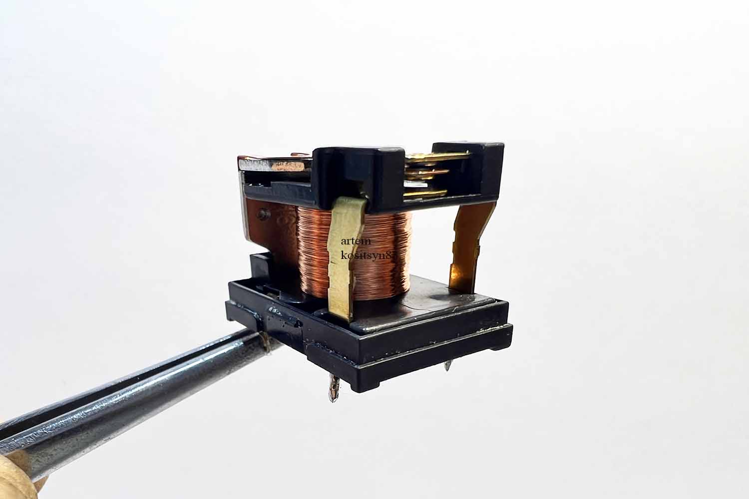
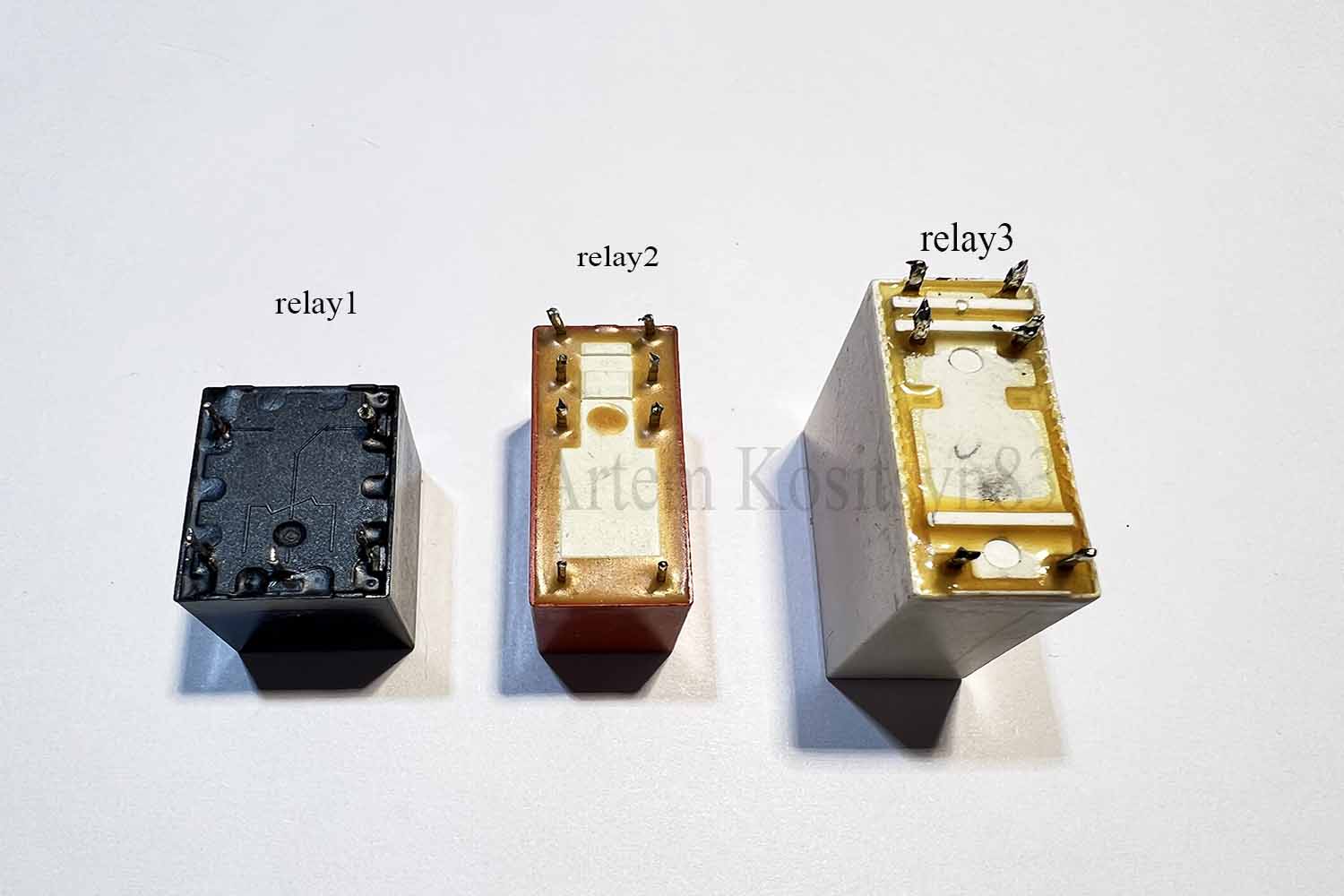
In this article I will tell you how to make 10 simple relay devices.Basically, I will use the relay number 1, relays 2 and 3 will be in two circuits.
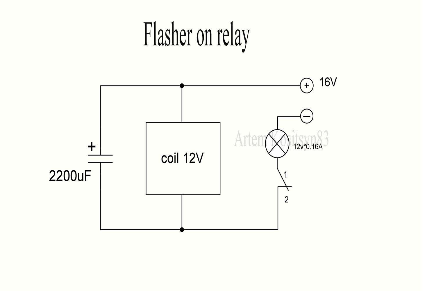
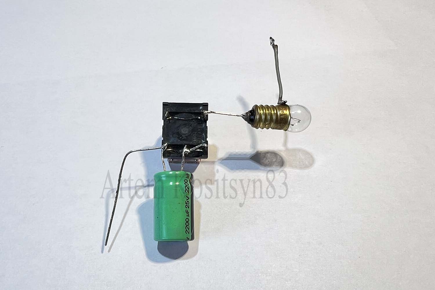
The first circuit is the circuit of the flasher on the relay.The lamp will flash, and the flashing frequency depends on the capacitance of the capacitor.The larger the capacity, the lower the frequency.The lamp should be on a small current.The scheme works like this:when power is applied, the relay contacts move away, but the charged capacitor is discharged onto the relay coil and the contacts are attracted again, while the capacitor is discharged and the contacts move away.
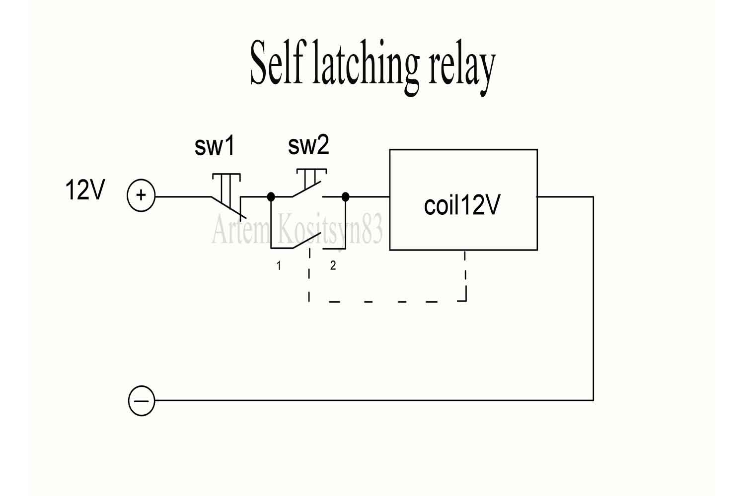
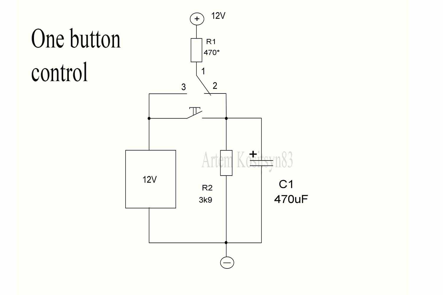
The second circuit is a self-latching relay.When the power is on, the relay does not work.Press the sw1 button and the relay is triggered and blocks the button with its contacts.To turn off the power, press the sw1 button.Apply button 3
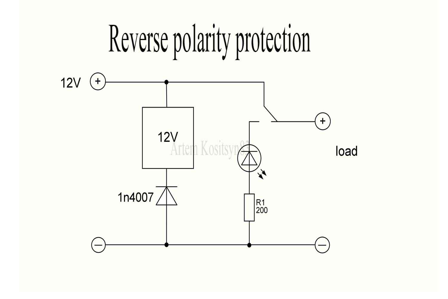
The third scheme is the protection of the load from the reverse polarity of the power supply.If the power supply is correct, the relay does not work and the current goes to the load.If the power supply is incorrect, plus goes through the anode of the diode and the relay coil, the relay is triggered and switches its contacts to the LED.The LED is shining and the current does not go into the load.
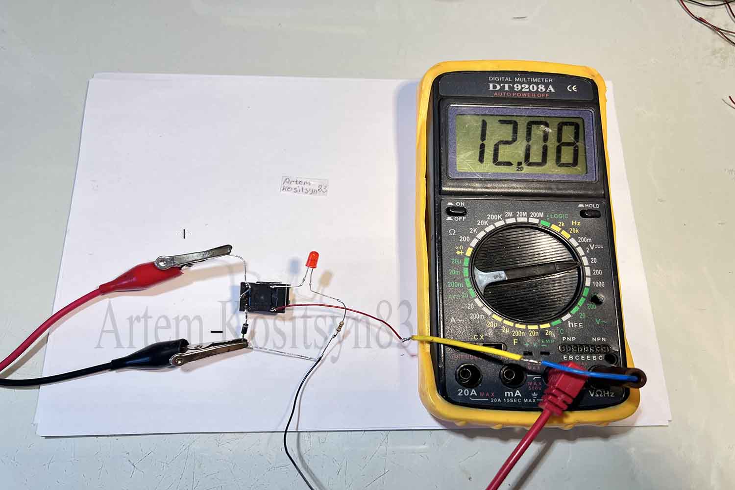
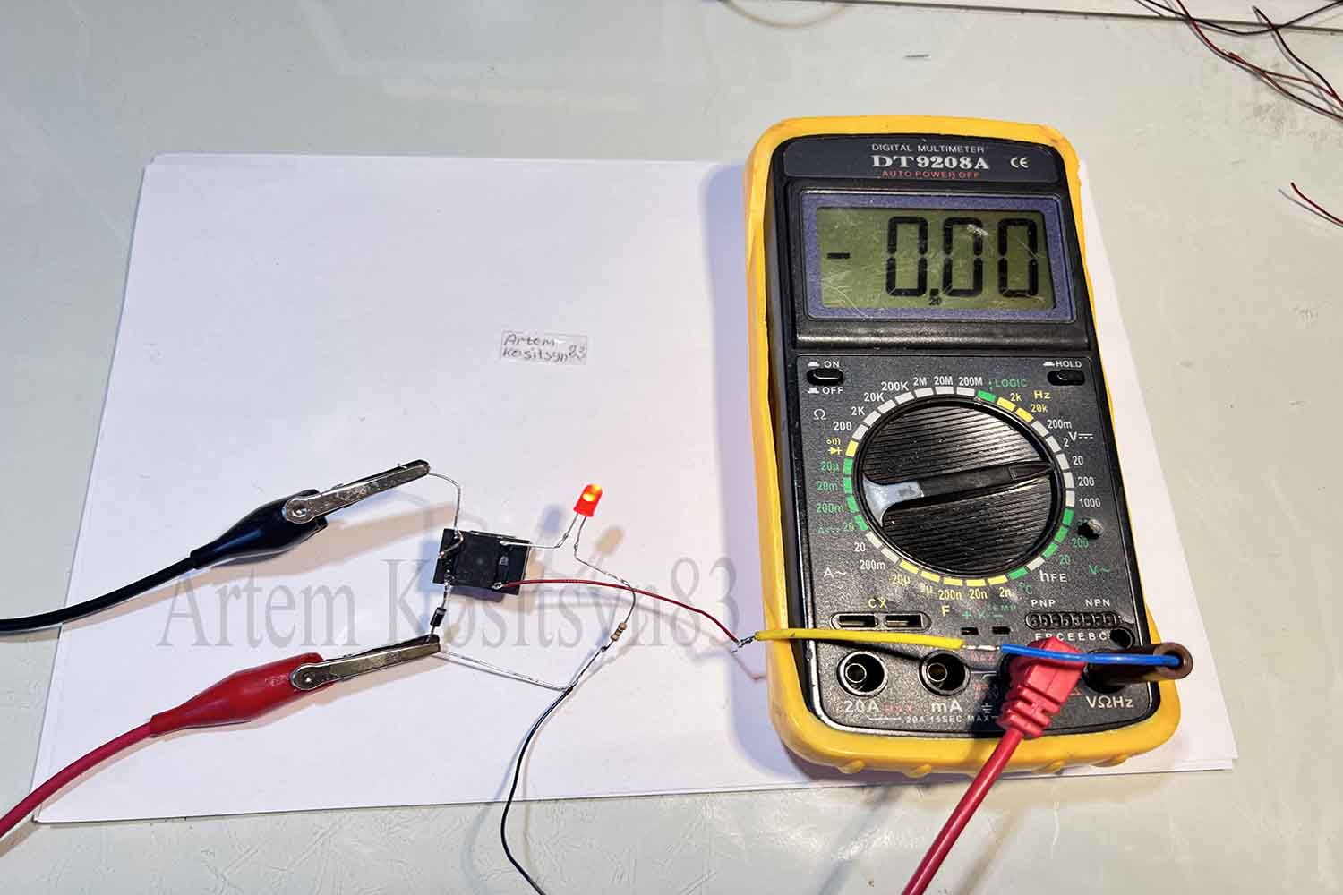
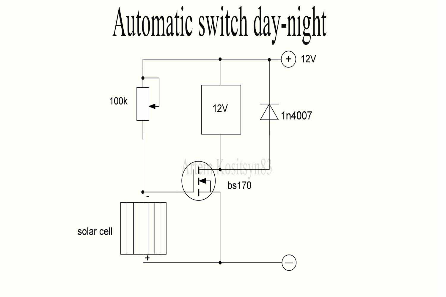
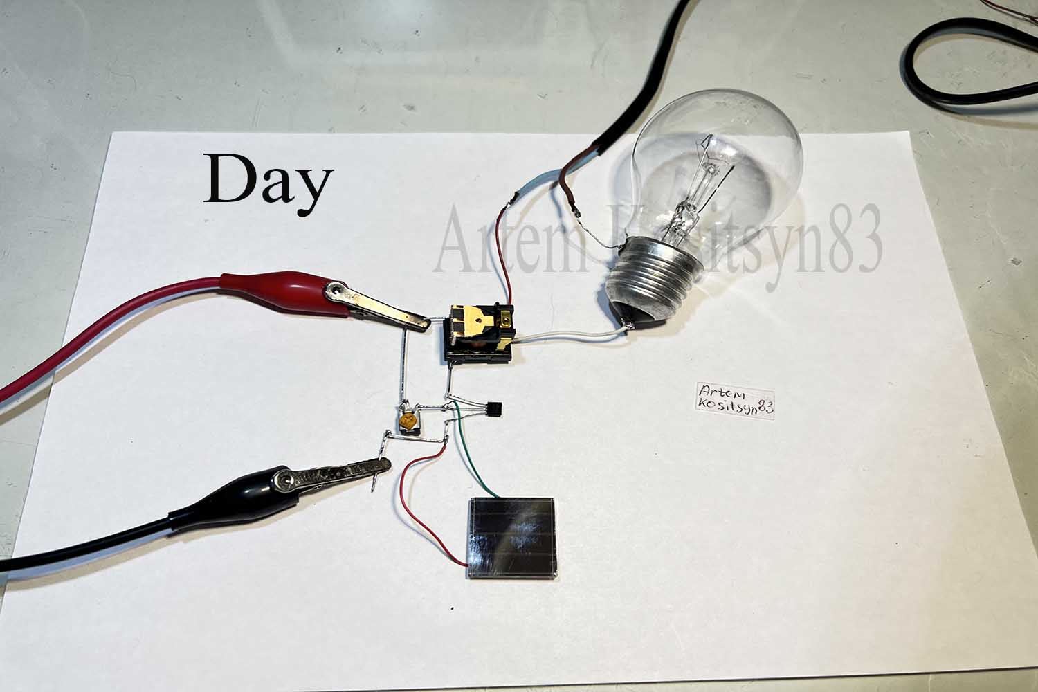
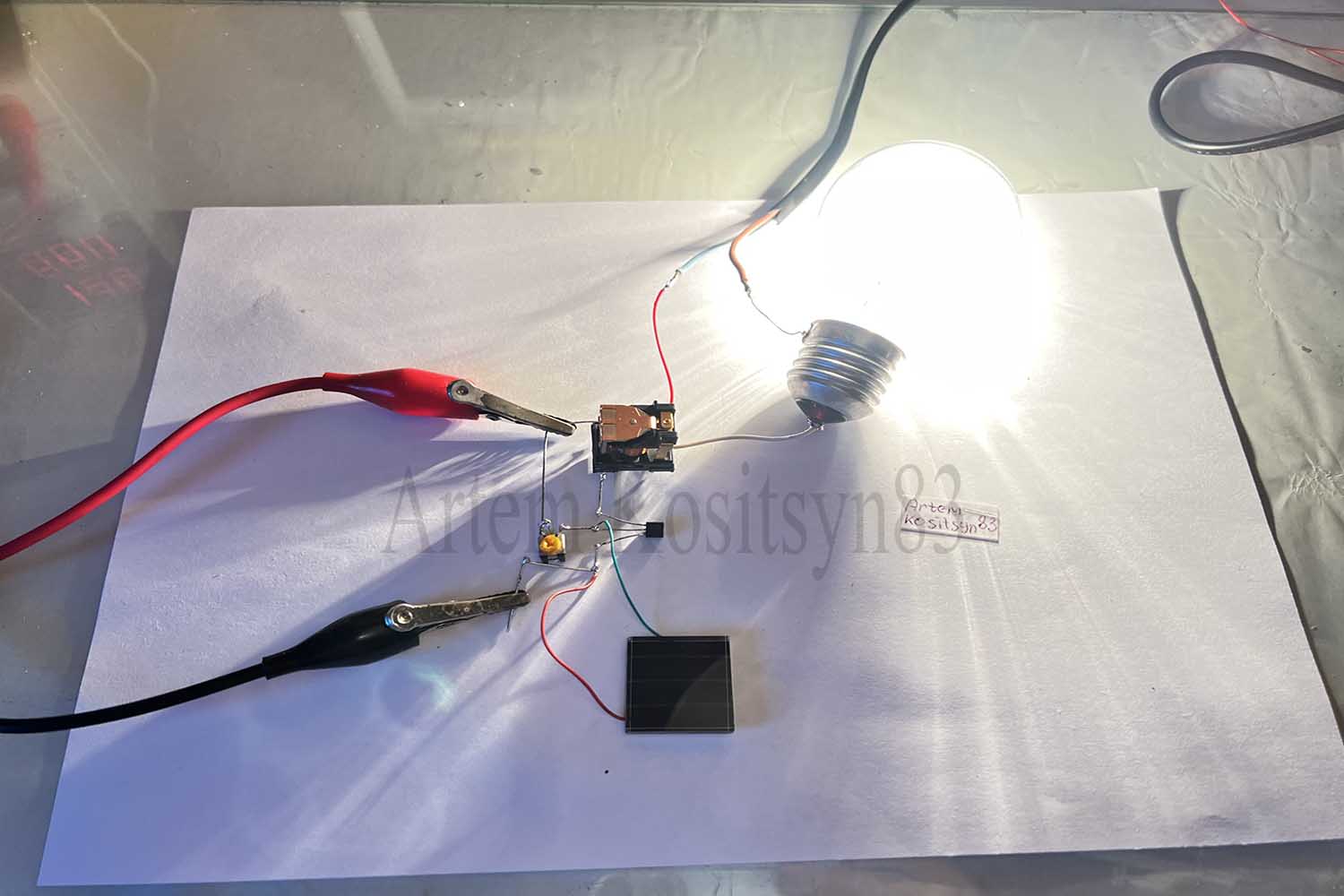
The fourth circuit is an automatic day-night switch.The resistor must be set to the normal sensitivity of the device.When the light shines on the solar cell, the transistor is closed and the current through the relay coil does not go and the lamp does not shine.When it is dark and there is no light, the transistor opens and the relay is triggered, the lamp shines.
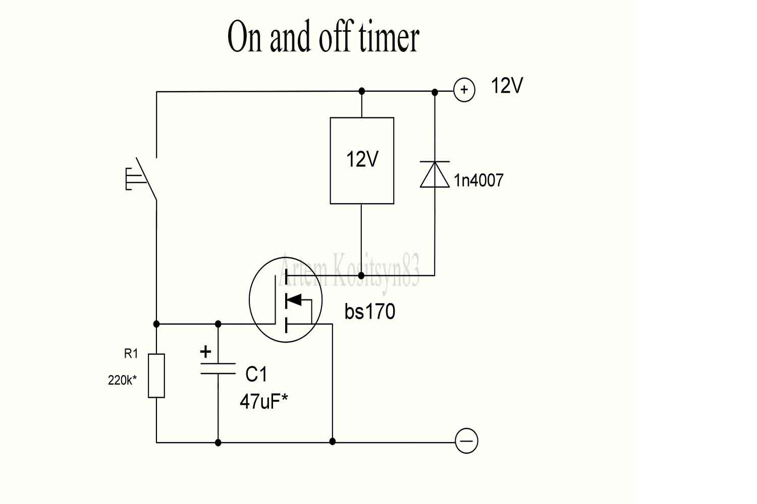
The fifth circuit is a time relay.We press the button, the capacitor is charged and the transistor is open, the lamp is shining.Press the button, the transistor will be open until the capacitor is discharged.The resistor and capacitor must be selected at the right time.
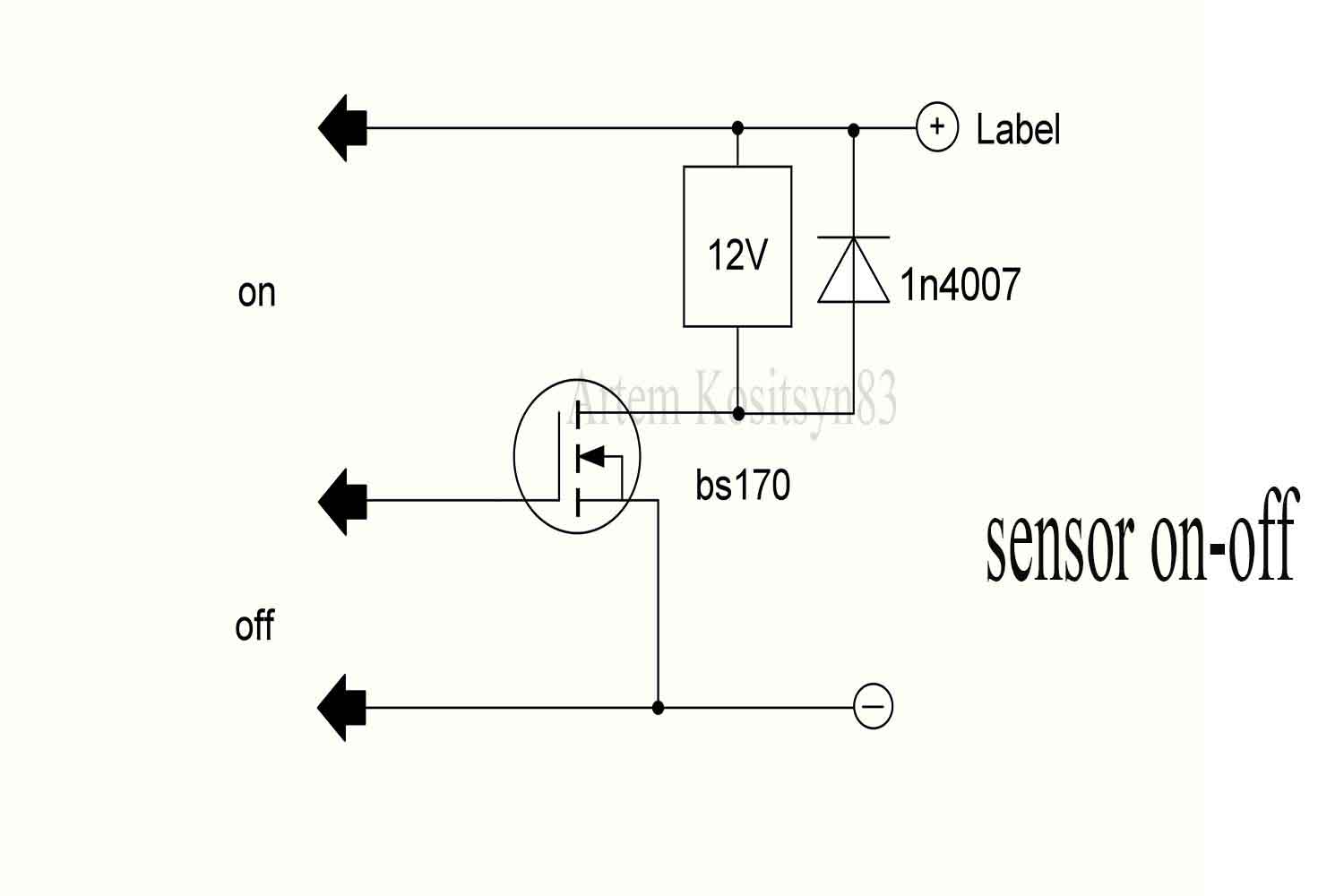
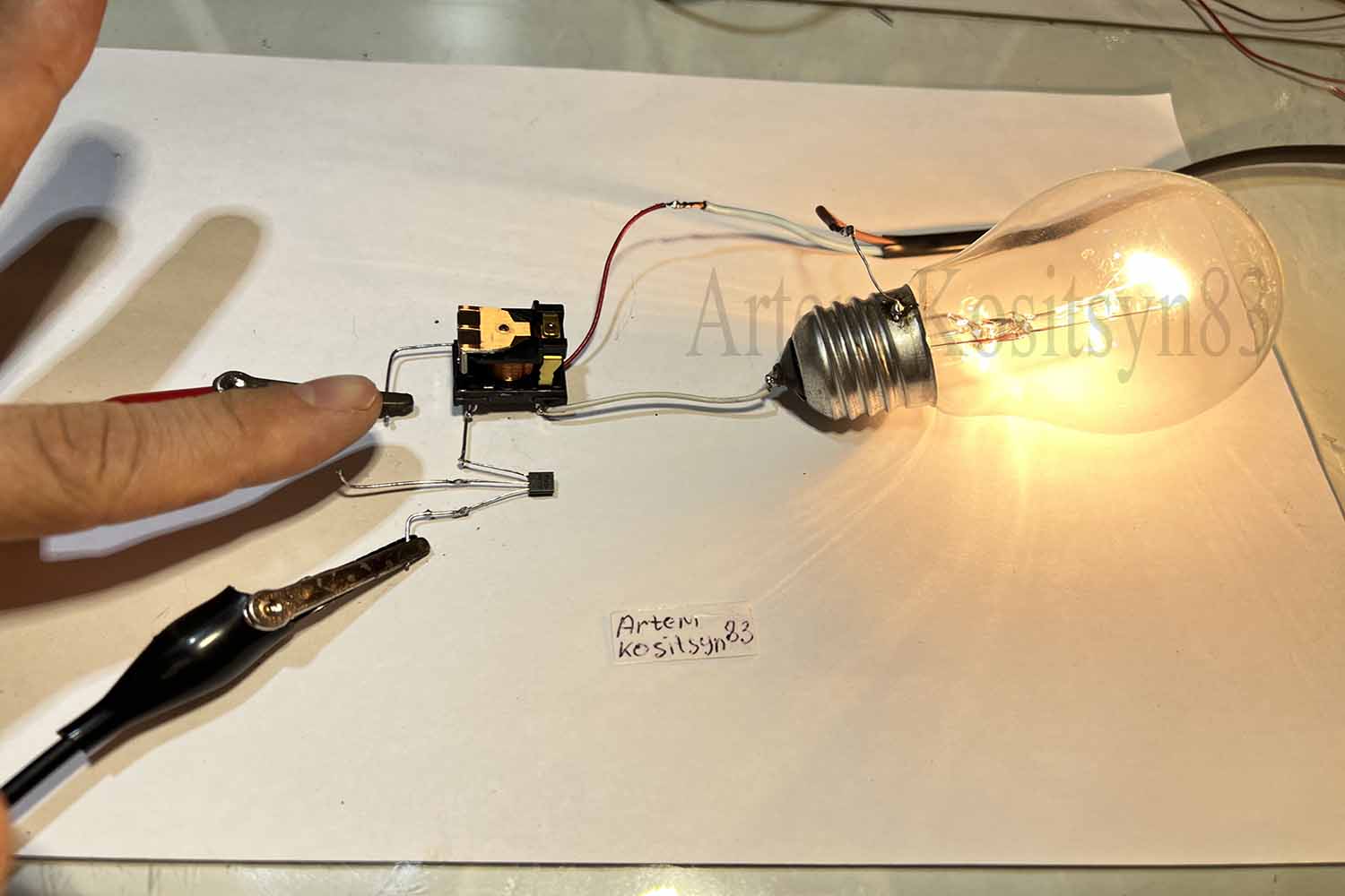
The sixth circuit is a simple touch switch- load switch.Touch with your finger plus power and shutter and the transistor opens and the lamp shines.The glow time of the lamp depends on the shutter capacity.To turn off the lamp, touch the shutter and the negative power supply.
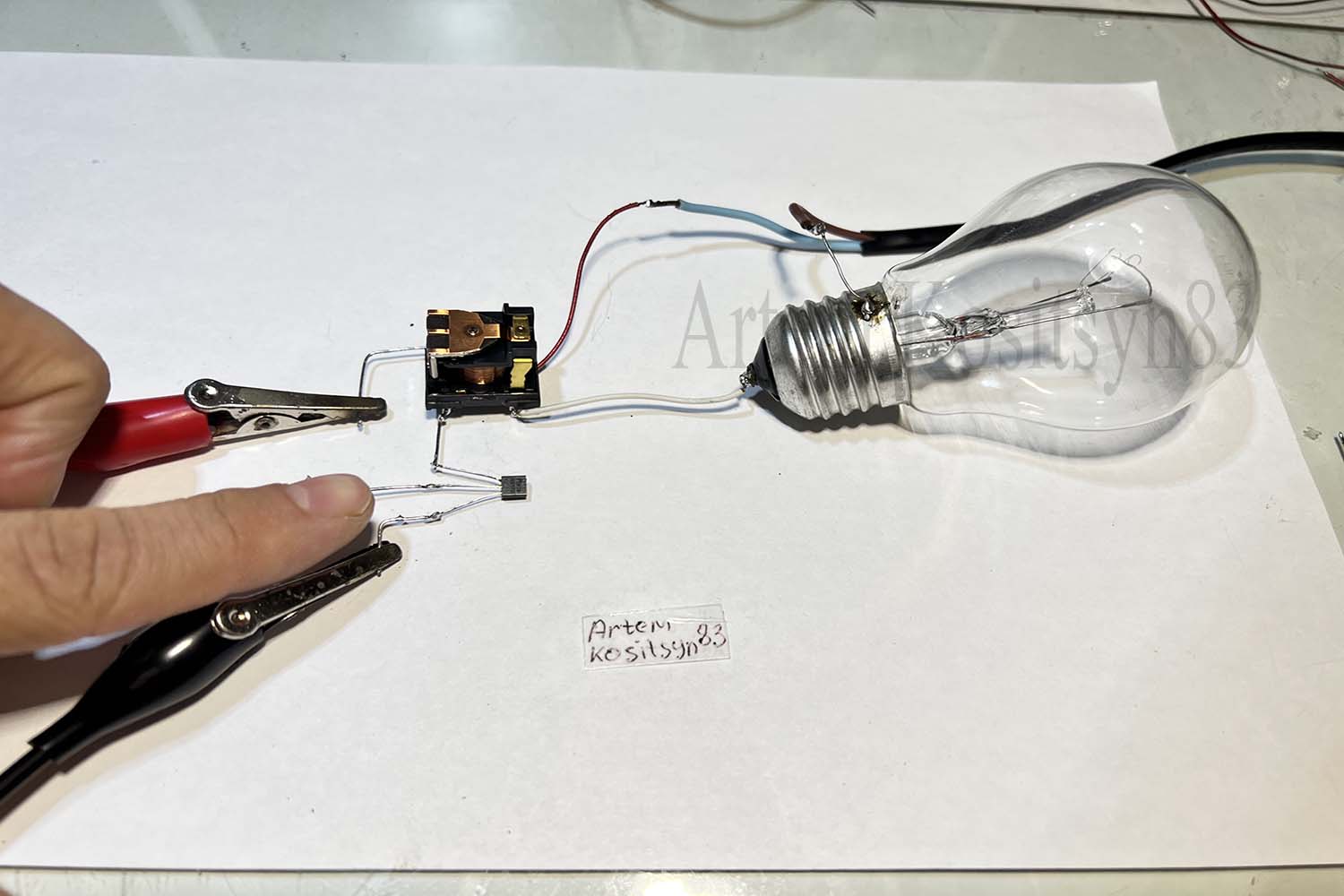
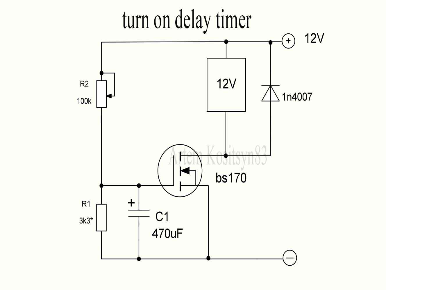
The seventh circuit is a relay with a delay in switching on the load.We supply power and the transistor will be closed and the lamp does not shine.After a short time, the capacitor will charge and the transistor will open.This time should be selected with a resistor and a capacitor.
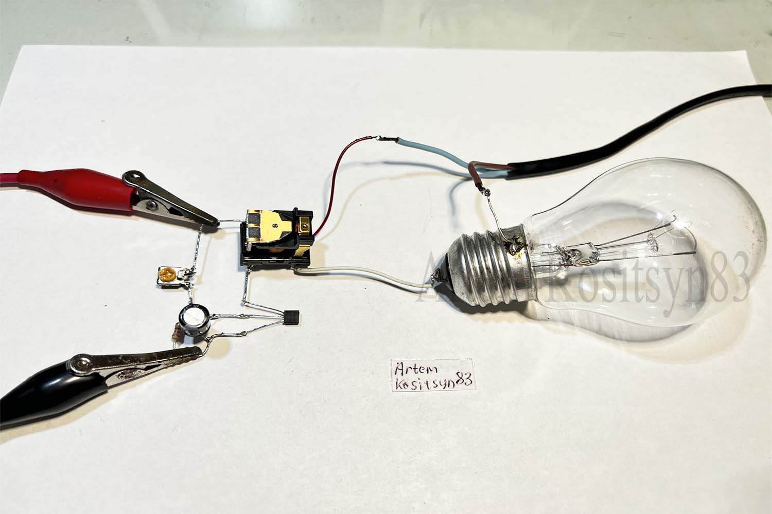
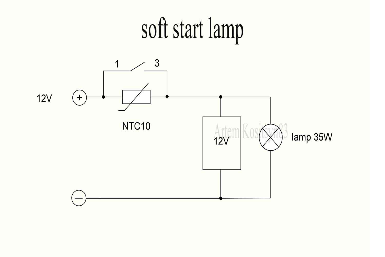
The eighth circuit is a smooth start of the load or lamp.We supply power and the relay does not turn on and the current to the load goes through a resistor with a negative temperature resistance.The resistance of the resistor from heating drops and the voltage on the coil increases.Next, the relay is triggered and the resistor is shunted with its contacts.The soft start time depends on the load current, resistor resistance and relay winding.
The ninth circuit is one-button control or on-off.Apply relay number 2
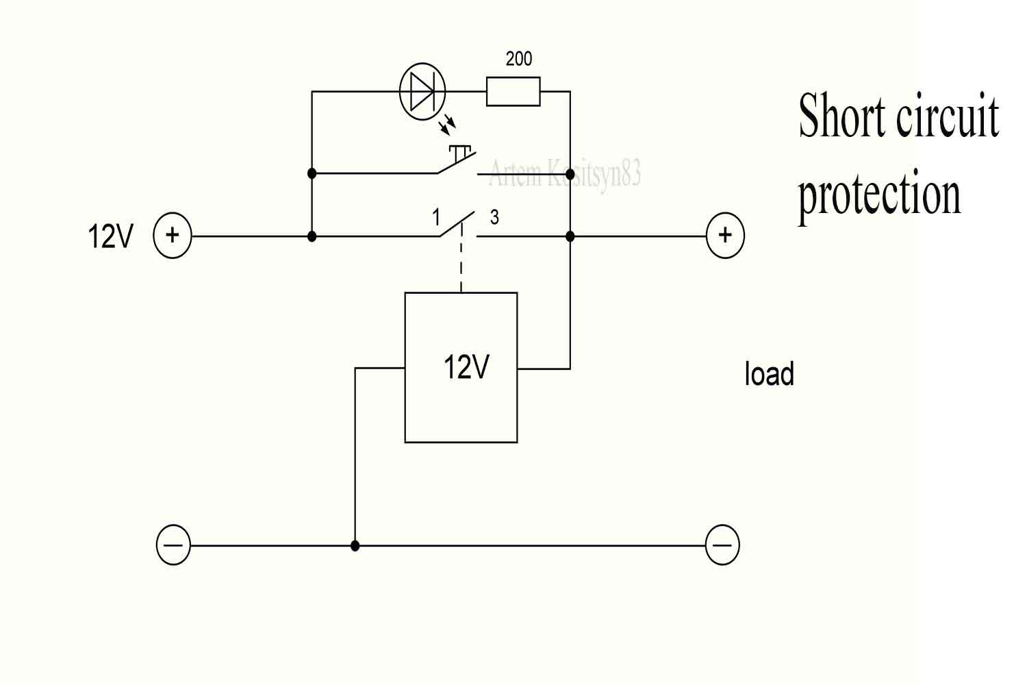
The tenth circuit is a short circuit protection on the relay.When the load is not connected and there is no short circuit, the current through the relay coil does not go.We connect the load and briefly press the button, the current goes to the load and the relay is triggered.In case of a short circuit, the relay winding is shunted and the relay releases the contact, thereby de-energizing the load.Pay attention to the button, it must correspond to the load current, because when you press the button, current flows through it to the load for a short time.