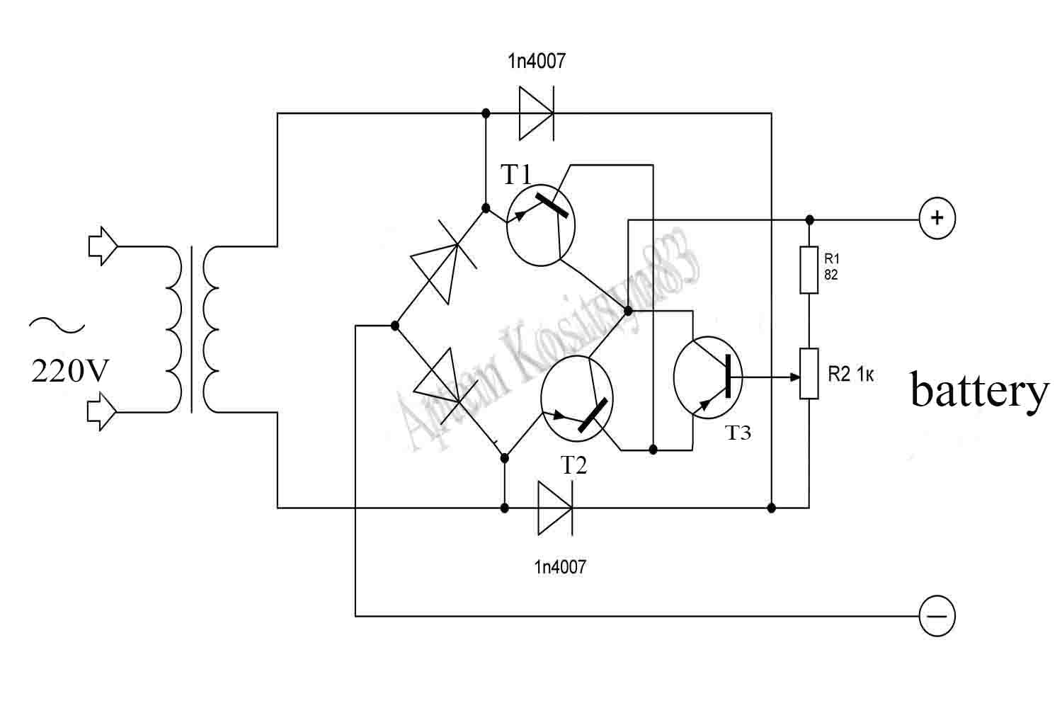
A simple battery charger, with which you can charge them and adjust the current at the output of the battery.The device is not assembled very according to the standard scheme, two transistors are installed in the diode bridge instead of two diodes.
T1-T2 transistors replace two diodes.With the variable resistor R2, we adjust the bias current to the transistor T3.This transistor, in turn, regulates the bias current on the T1-T2 transistors, thereby regulating the current of the diode bridge and the actual charging current of the battery.Diodes 1n4007 rectify the current to supply bias to T3.
The maximum charging current depends on the winding of the step-down mains transformer and the current of the semiconductors-two diodes in the bridge and transistors T1-T2.Transistors T1-T2 have a collector current of up to 7.5 A,the forward current of the bridge diodes is 5A, and the winding current of the transformer TS-180 is 4.7 A. This means that the maximum charging current of my device will be about 5 Amps.If you need more output current, then install more powerful components.All power diodes and transistors, including T3, are installed on the radiator to remove heat.The voltage of the transformer winding must be higher than the voltage at battery, otherwise charging will not work.
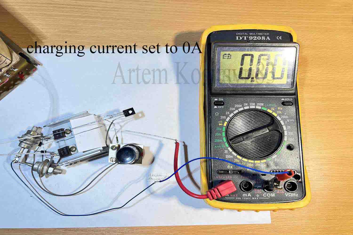
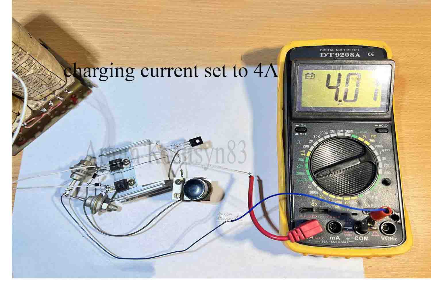
Checking the operation of the z.u. I connected an ammeter to the load instead of the battery, I set the current with a variable resistor.