For more than two years I have been using the well-known ESR GM328A tester and in this article I will tell you about the main functions of this device.Here we must immediately warn that testers are sold with different firmware, which means that some functions may differ from different testers.And also, when checking the capacitors, be sure to discharge them, otherwise you can disable the device.
Here’s what this tester can do
:
Check and show the characteristics of field-effect transistors Check and show the characteristics of bipolar transistors Check diodes and LEDs Check thyristors, but not all thyristors can be checked in my tester, their opening level is different Measure the resistance of resistors from 0.01 Ohm to 50 mOhm Measure capacitance of capacitors from 25 pF to 100 mF, their ESR and Q-factor Measure inductance from 10uH to 20H Measure frequencies up to about 2 MHz Check zener diodes with stabilization voltage up to 4.5 Volts There is a built-in rectangular signal generator up to about 250 kHz, then the signal is distorted There is a remote control decoder,an IR signal receiver is needed The rest of the functions cannot be mentioned, such as connecting a temperature sensor
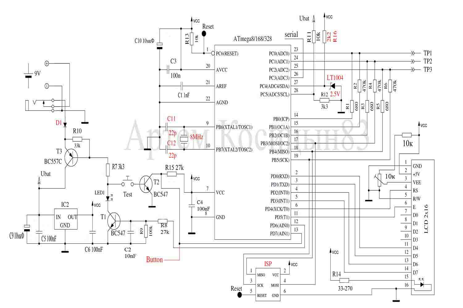
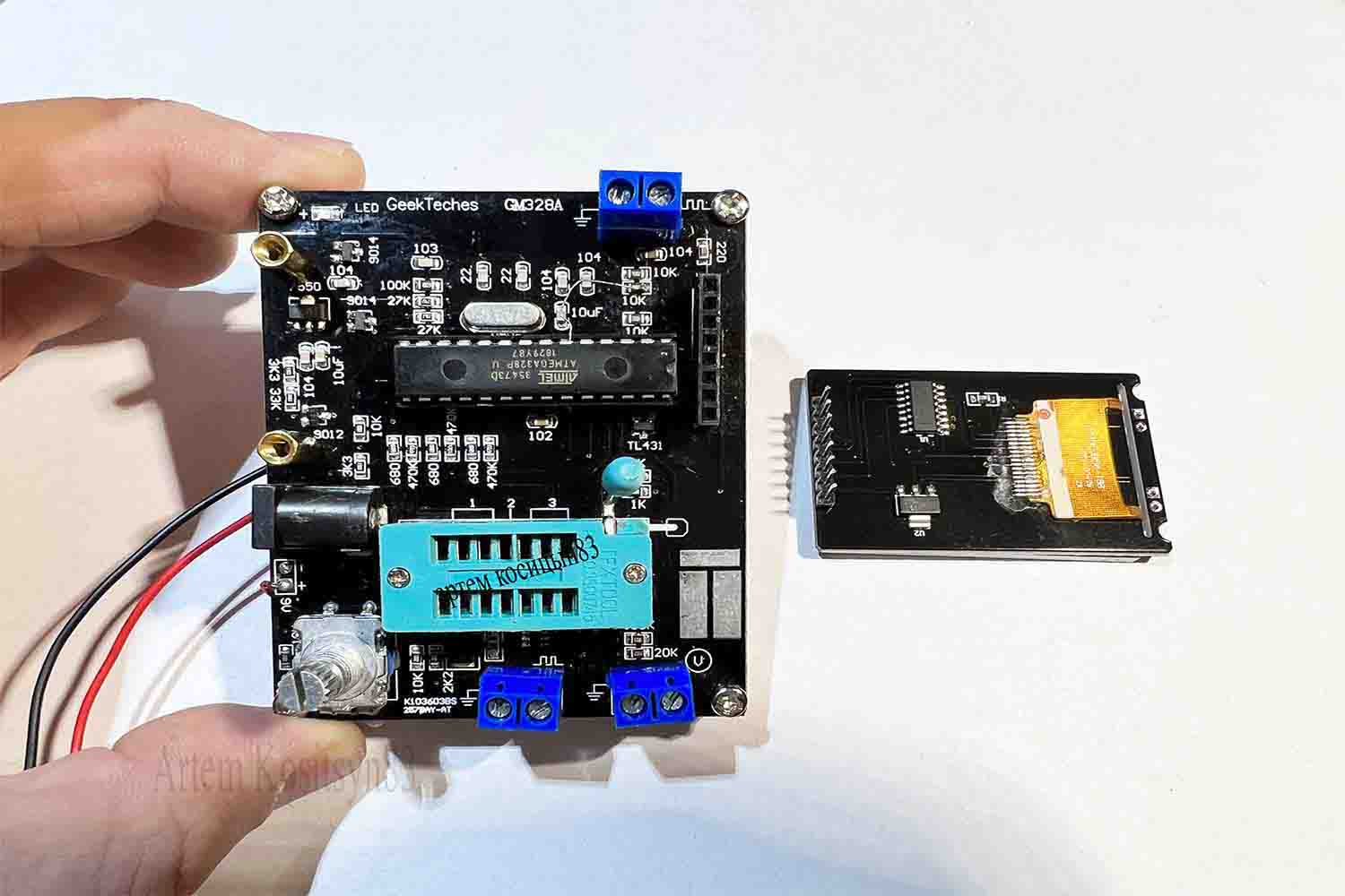
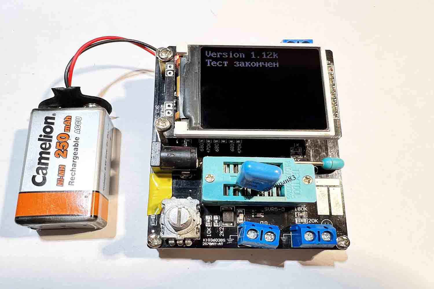
Here is the diagram of my tester with firmware 1.12.The tester is made on an Atmega328 microcontroller
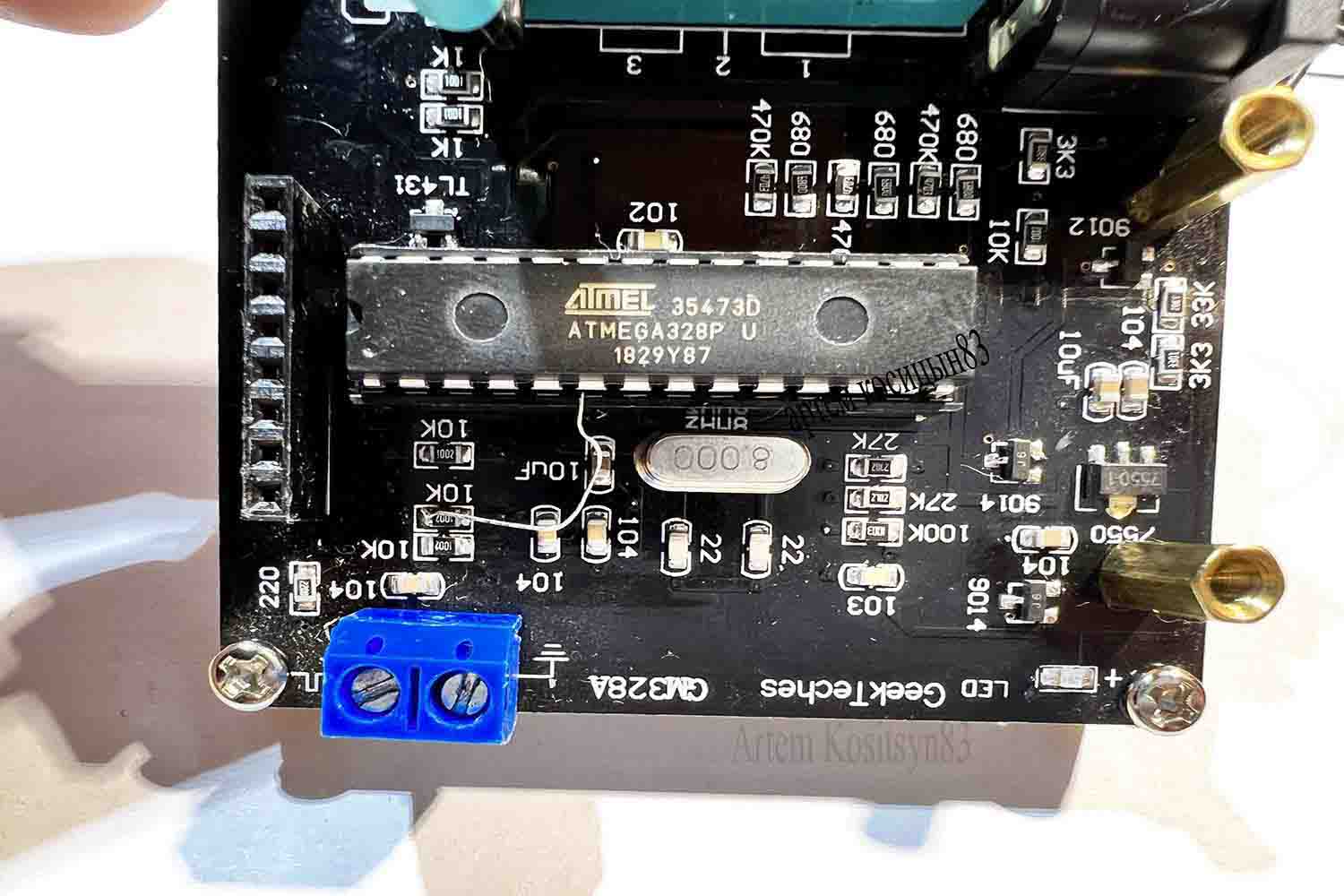
If the tester does not measure frequencies or the frequency meter does not work, connect pin 6 of the microcontroller to a resistor with a resistance of 10 kOhm, which is located on the board as shown in the photo.
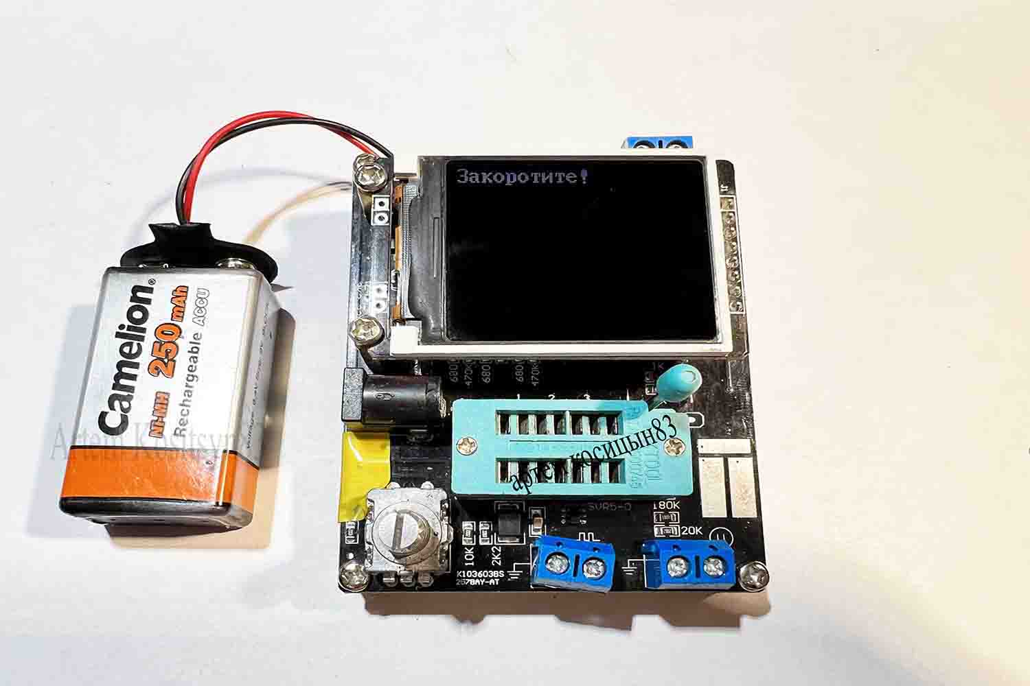
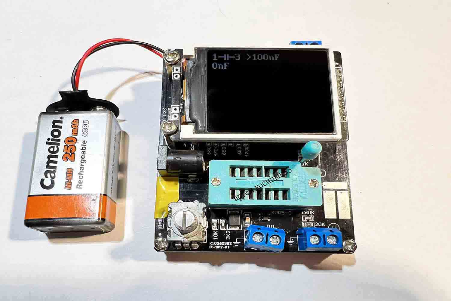
Before starting work, it is necessary to calibrate.Select the “Test” mode with the encoder and click on it.The inscription “short-circuit” will appear.
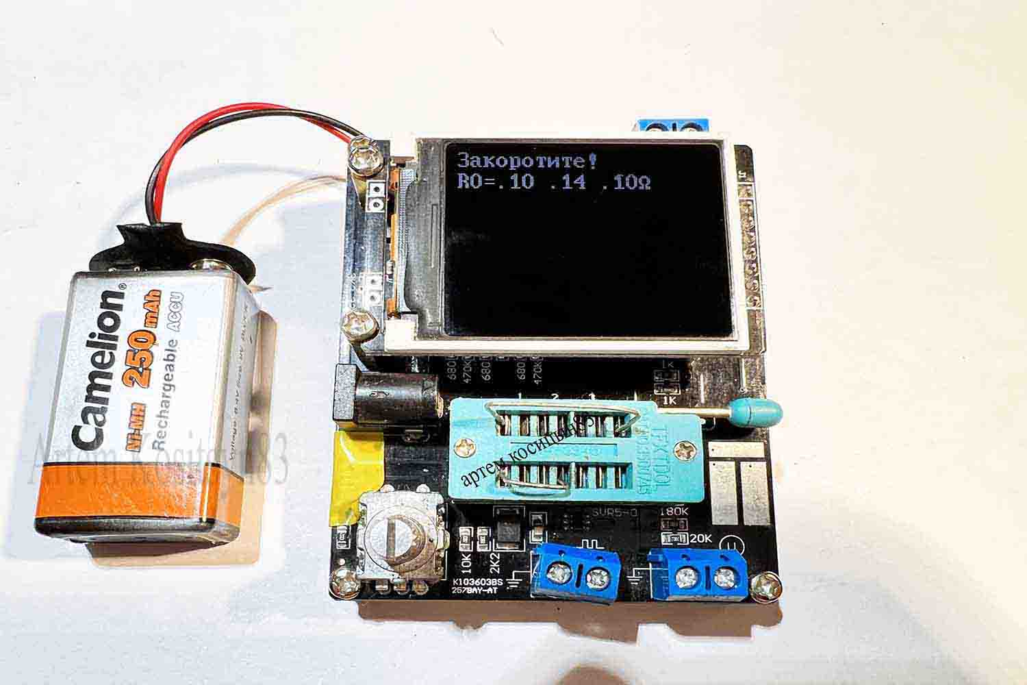
Short-circuit the terminals 1-2-3 with jumpers, as shown in the photo
Then, after various messages, the inscription connect a capacitor with a capacity of 100nF will appear
When the calibration or test is completed, an inscription will appear about it.Now you can start measuring.
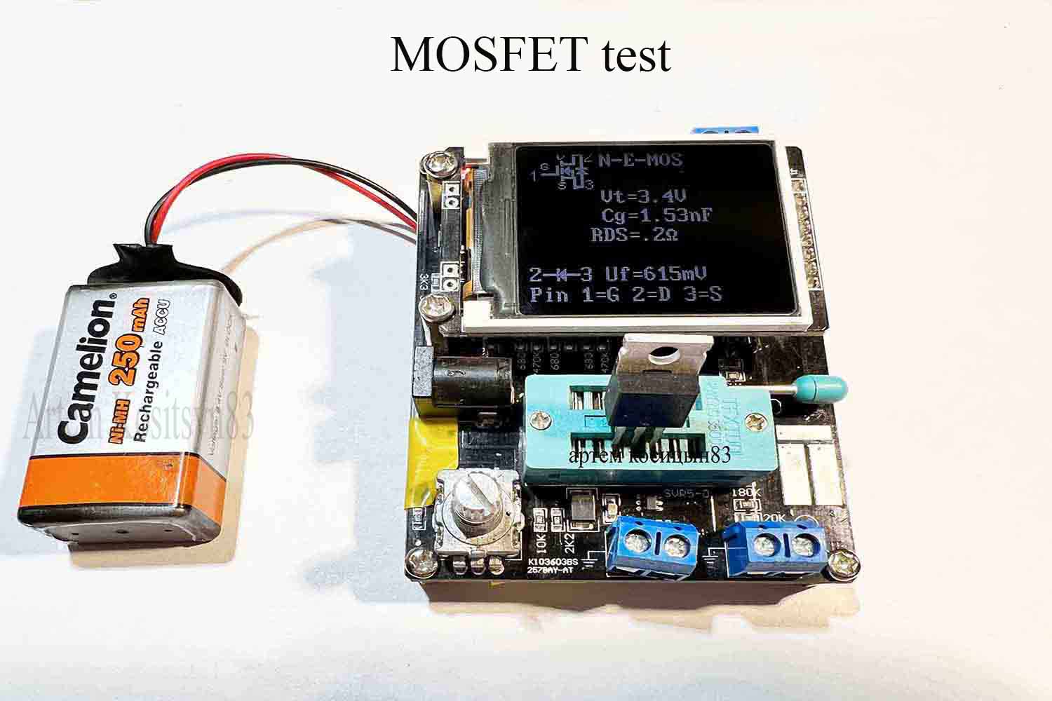
Checking the field effect transistor.The test will show its conductivity, VT is the voltage at the gate of the transistor opening 3.4 Volts.Cg is the capacity of the shutter.RDS is the resistance of the open channel.Next, the voltage drop on the diode, which is in the field-effect transistor and its pinout.Three contact pads are visible on the board on the right, these are the three outputs of the tester and you can also connect parts to them for verification.
Bipolar transistor test.Will show its conductivity.hFE is the gain factor.Next, the emitter current at a voltage based on 631mV and the reverse collector current and pinout pins.
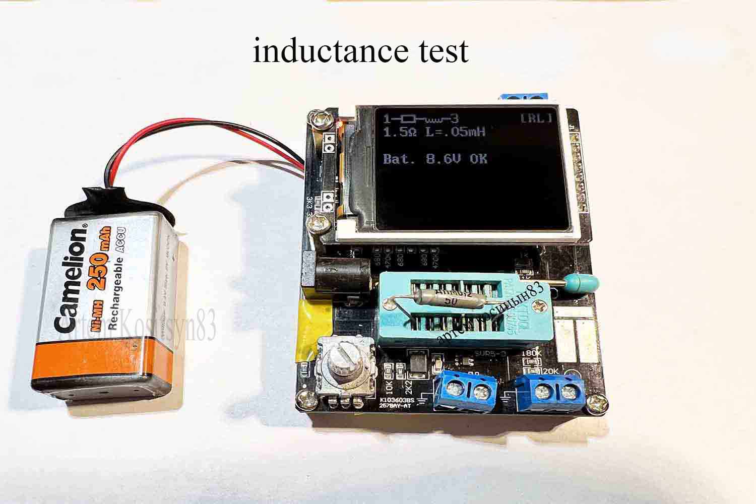
Inductance test.The throttle at 50uH shows as 0.05mH, which corresponds to 50uH.
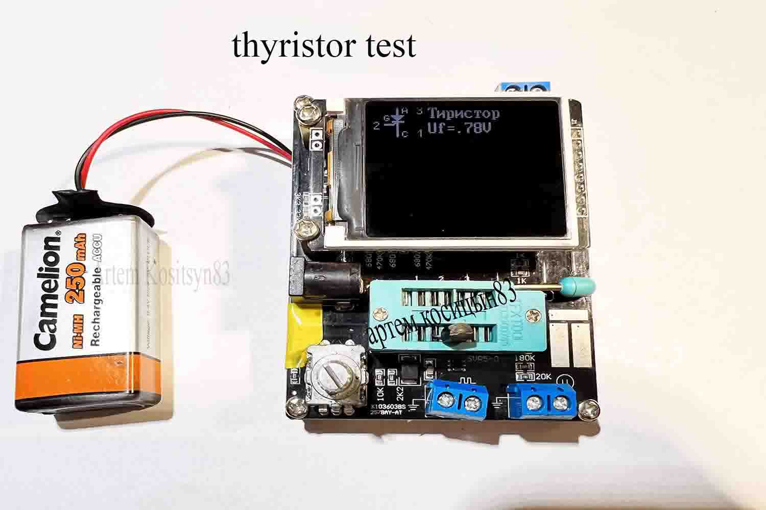
Test thyristor MCR100-6
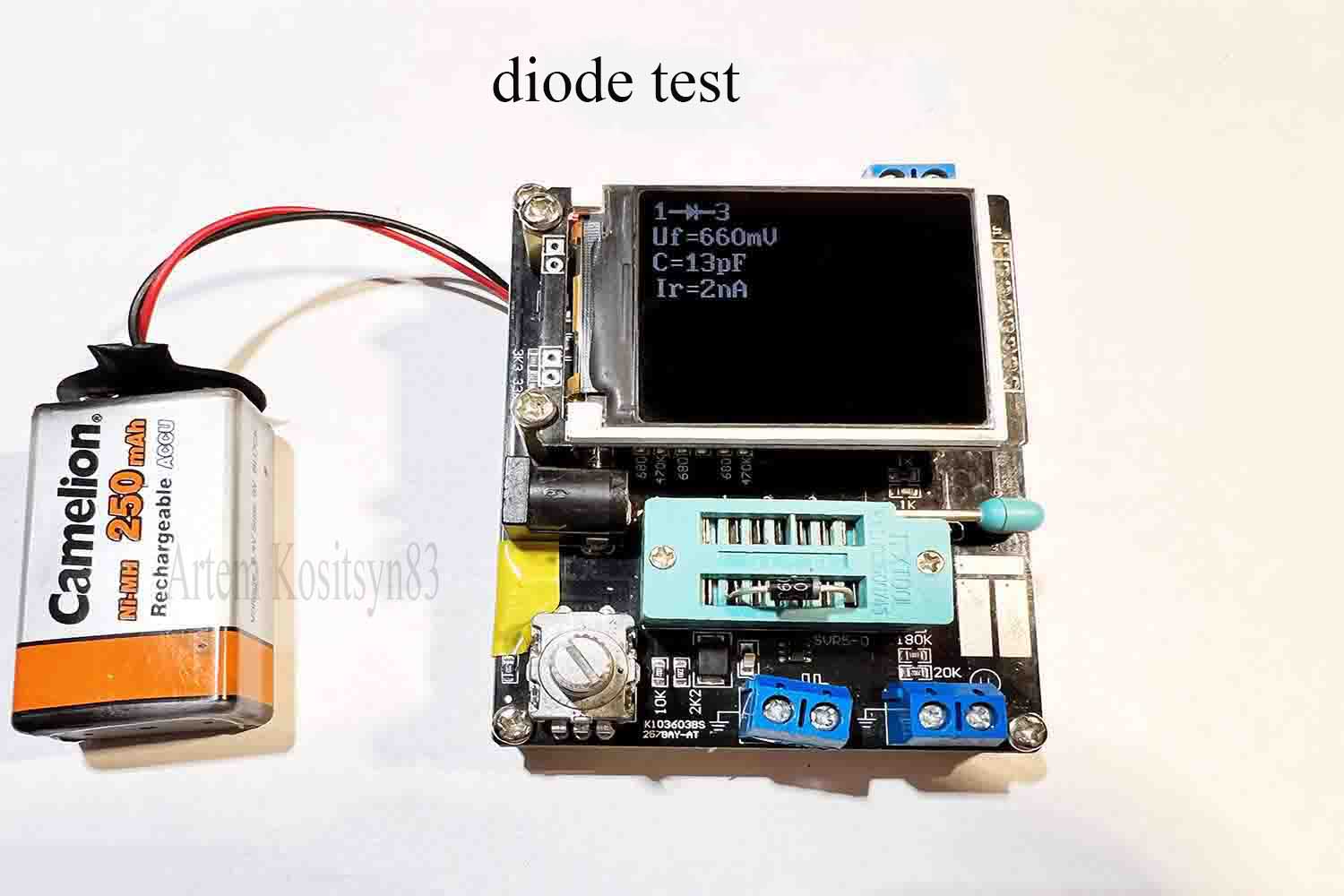
1n4007 diode test.Shows the voltage drop on the 660 mV diode and its junction capacitance
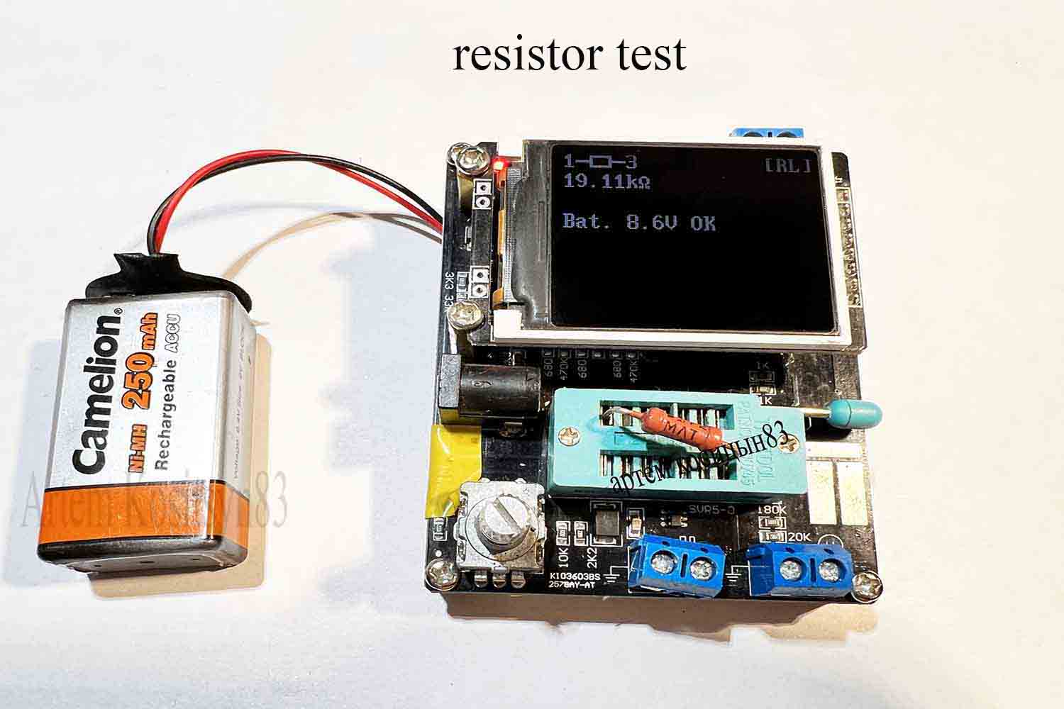
Resistor Test
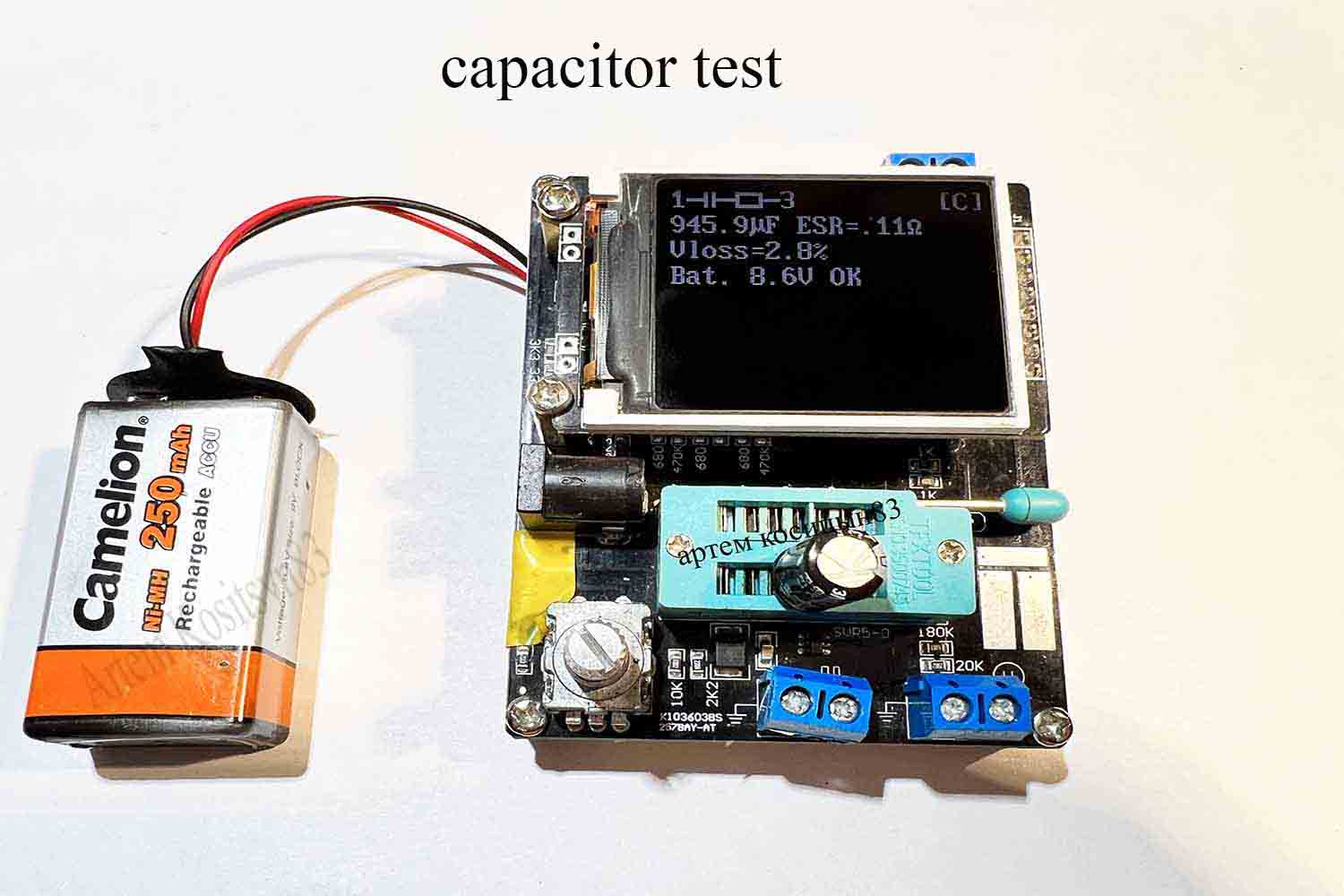
Oxide capacitor test.ESR is the equivalent series resistance.
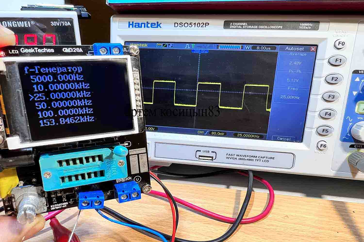
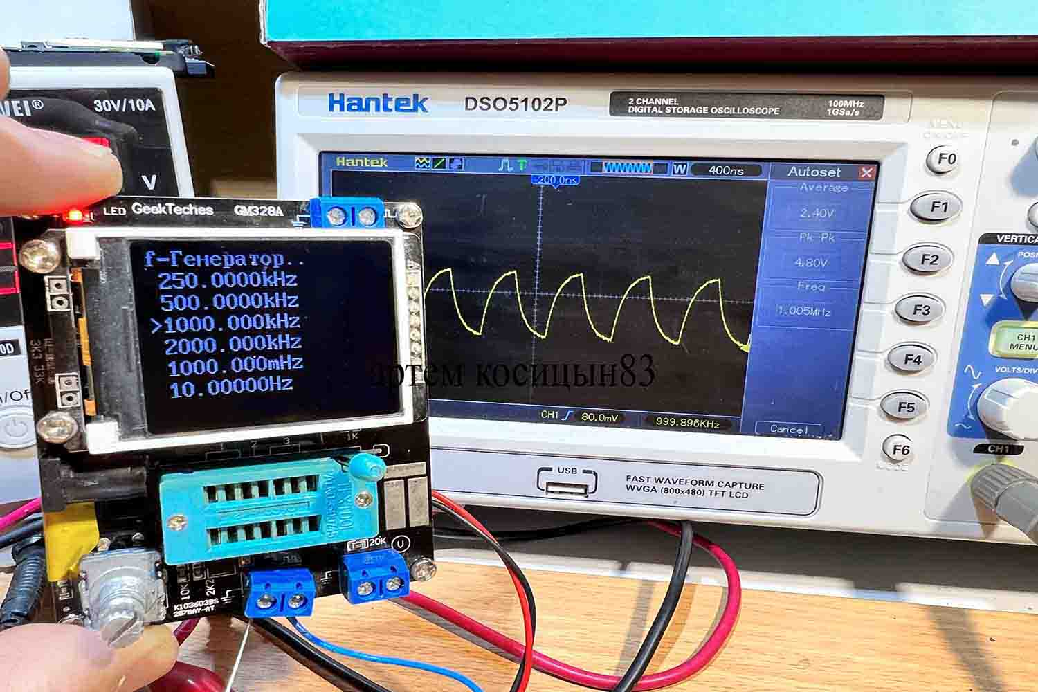
The signal generator outputs a signal with a frequency of up to 2 MHz.At a frequency of 1 MHz, the signal does not look like a meander.At 25 kHz and up to about 250 kHz there is a meander at the output
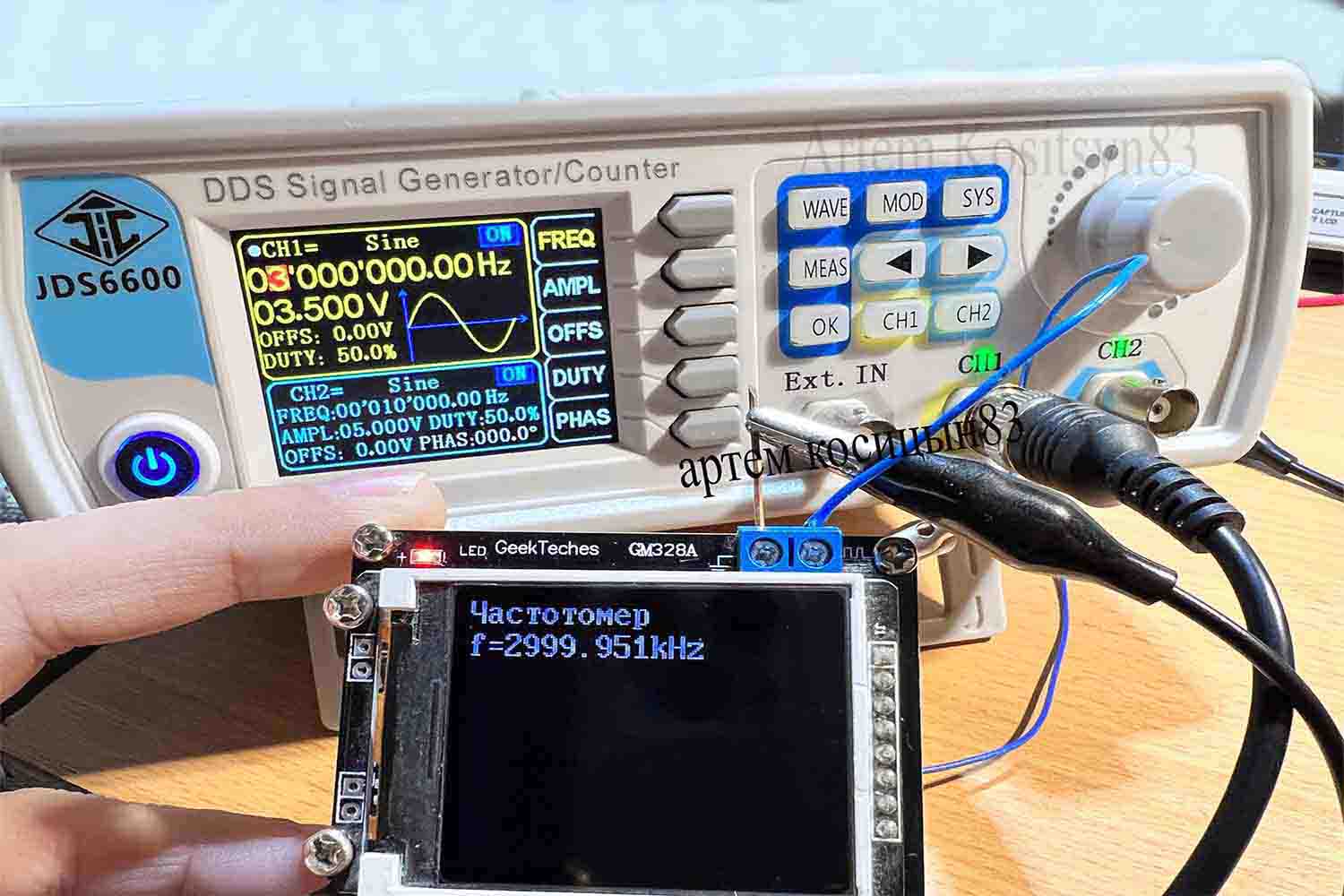
Checking the frequency meter function.In my tester, it measures frequencies up to about 3 MHz, but up to 2 is exactly more or less normal.The signal is given with an amplitude of 3.5 Volts
I don’t need the voltmeter function, and other functions, and I don’t need to consider them.In general, the tester is excellent and is quite justified for its cost.